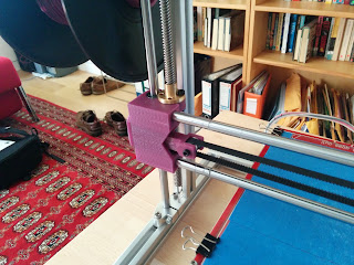
- move the motors above the frame of the printer, thus reclaiming some vertical space.
- replace the 5mm threaded rods by 8mm lead screws for smoother and more accurate operation.
- place a bearing under each motor coupling for support.
- replace the extruder carriage with one that has four bearings and a better grip on the GT2 belt.
- replace the X axis end pieces (motor mount and idler) with ones suitable for the lead screws and which also have screws to hold the bearings more tightly.
- add an X belt tensioner to the idler.
Here are some pictures of some of the parts and the overall construction.
I bought the lead screws and the 608ZZ bearings that go under the motors couplings from Bangood, and the couplings themselves from Folger. I got new LM8UU linear bearings from MakerGeeks.com. They came very oily, unlike the original Folger ones which were quite dry. I also smeared a small amount of white Lithium grease inside them using a q-tip.
I printed all the parts myself. Before taking the printer apart for the rebuild, I checked the prints: were all the holes big enough for the M3s screws, did the bearings fit, did the chrome rods fit, etc. Initially the chrome rods did not fit in the X motor mount, so I reprinted it with a 0.9 extrusion multiplier. The tensioner was too tight in the idler bracket (that's the one on the left), so I sanded it down slightly. I am slightly concerned that they belt rubs on the X carriage as you can see above, so that may need a little sanding down as well. Note that I have used cable ties on the belt, though they are really not necessary, as the teeth mesh and hold the belt quite firmly.
There were a few hairy moments during the rebuild. I first assembled the motors onto the motor mounts and then tried to join everything up, but it was really hard to get things square. In the end my sequence of steps was:
- assemble the X carriage apart from mounting the extruder. This includes the nuts for the lead screws, but not the lead screws themselves.
- put it on the vertical chrome rods, loosen the top part of the frame, get it in place, and reattach the top part of the frame loosely.
- attach the motor mounts without the motors.
- put the bearings in the motor mounts, then get the lead screws into place.
- attach the motor couplings and the the motors.
- gradually get things square and tighten everything up.
Then do the usual setting of the end stops and levelling the bed.
I made two small additional changes. As I mentioned in an earlier post, the end stop brackets that Folger supply are not so great, as the bracket extends some way above the top of the switch PCB. This can cause the switch to never trigger, as whatever is supposed to hit the end switch (the X motor mount specifically) will hit the bracket first. I adapted the bracket to move the holes where the switch attaches up a bit, so the lever of the switch now extends well beyond the top of the bracket. Also, I adapted the X motor mount in blender to add a small cylinder to the bottom of it, into which a M3 bolt can be attached. Then I added a larger plastic head to the bolt, so now I can fine tune the position at which the Z end stop engages without having to move the bracket. It looks like this:
The configuration in Marlin has to be changed to specify new Z steps settings. I thought the pitch was 2mm, which according to this would mean 1600 steps per mm. It was wildly off, and it's because I didn't understand the specification for the lead screws. They have a 2mm pitch but 4 starts, in other words there are 4 intertwined spiral threads. So one turn is actually 8mm, and we want 400 steps per mm, giving this line in Configuration.h: #define DEFAULT_AXIS_STEPS_PER_UNIT {80,80,400,97.826}
Does it work? Yes! I haven't printed a lot yet, but enough to see that it looks OK. I printed 10mm calibration cubes at 0.3mm, 0.2mm and 0.1mm layer heights, and even at 0.05mm, which I've never managed to do before (with a first layer of 0.15mm to make it stick). The Z movement is very quiet, and the X movement is quieter than it used to be. I also printed a thin walled cube and a few miscellaneous other objects. I can raise the Z position to 150mm, whereas before I could only go to 120mm before worrying the mechanism would tear itself apart. There were are few clunking noises, probably motor skips, and I think I could just have got to 160mm.
Thank you wderoxas for the designs, and also CheopisIV for these pictures of another build.


2 comments:
I've searched and cannot find that 4 linear bearing X carriage extruder mount plate anywhere (thingiverse too!)
please help.
ty
-Wes
I don't think the X carriage ever made it onto Thingiverse. I got it from this google drive folder (https://drive.google.com/folderview?id=0B6-qn0LXvv2QU0lCTDRKaTdSNlE&usp=sharing), linked from this post (http://forums.reprap.org/read.php?406,512329,535457#msg-535457).
Post a Comment