One though which follows is that you could made the drive shaft better by printing it and the sprocket with a non-round cross section, like the flattened shafts you get on some stepper motors. They probably would not last as well as the steel ones, but it's an interesting idea, as you can cut the plastic to the exact length very easily.
Sunday, July 16, 2017
3D Printed Tourbillons, a coda
In my previous post, I wrote about making 3D printed tourbillon mechanisms. There are a few parts in these designs which are not printed, specifically two small bearings, and a few 2mm and 3mm shafts made of steel. There is not much I can do about the bearings, but I was curious to see if I could replace the shafts with plastic and used them in the version III design. I printed 1.8mm, 2mm and 2.8 mm diameter cylinders at 0.1mm layer resolution. They had to be printed with brim, so I then trimmed the brim off with a sharp knife and lightly sanded them. The 1.8mm shafts work quite smoothly for the spring/balance wheel, the escapement gear and the anchor. The 2mm shafts replace the two shafts which hold the frame together. The 2.8mm is a replacement for the the main 3mm shaft. It's a tight fit in the bearings, and is also too loose for the sprocket to engage with it well. I tried to shim it with a little blue tape the way I had done with the steel shaft, but this didn't work. However, putting a small blob of blu-tak (or similar) in the axis hole of the sprocket did. Here is the tourbillon working with plastic shafts (which I wave at the camera at the start).
Saturday, July 15, 2017
3D Printed Tourbillon
I've tried several times to print clocks and clock mechanisms, with not much success. Here are three models that I tried:


I printed the first with my original Folger 2020 and the other two with my Eclips3D. None of them ran very well: the clocks would tick for only a few seconds, and the tourbillon watch would not run at all, though I was able to get the tourbillon subassembly to work for a short while.
I don't really know how to debug mechanical systems. With code, I have intuitions about where to start looking and techniques that I've learned over the years for breaking down and isolating the problem. But with most mechanical systems of any complexity, I don't really know how to get started, apart from looking for obvious things such as malformed parts. With a tourbillon, the problem is particularly hard as it isn't a linear sequence of parts, unlike (say) the spring motor, where each gear just turns the next one. In a tourbillon you have a power source which turns a mechanism, and the mechanism gets blocked from turning beyond a point by the anchor, and this causes the balance wheel to turn and then bounce back, nudging the anchor and allowing the mechanism to turn further, consuming a bit more energy from the power source. If any stage goes wrong, the whole thing just deadlocks. In the context of the tourbillon watch, this is made much more complex by the gears to divide down from seconds to minutes and hours.
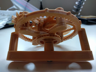
I like the tourbillon as a design. It just looks interesting when it's moving. So I was happy to find a couple of designs on thingiverse for just the core tourbillon on its own. Here is one. And here is the other. I spent last weekend working on the first one, and almost gave up when it didn't run at all. But unlike the toubillon watch, the mechanism is simple enough that I could look at it part by part and see which parts weren't moving freely or slipped slightly on their shafts under load. With some reprints and adjustments, it worked: not perfectly, but enough that I had some confidence that continuing to tweak it would fix it. When it does stick it is always at the same position, implying that either there are some gear teeth that need adjusting, or possibly that the weight of some of the parts throws the mechanism slightly out of alignment. Here are some pictures and video. It's a bit wobbly in the wideo, and I have since improved this.


I then went on to the other design (it's called design III - the person who made them recommends not trying version II). Again, it took some fiddling and reprinting parts which were a little off. I think this is a less good design than version I. In particular, the power transmission from the sprocket (the wheel with the dimples) is done purely through the shaft that it is attached to. This means it slips quite easily, and once it has slipped a few times, the wear on the inner hole of the sprocket means it will keep slipping. In version I, the sprocket was locked to the mechanism through a hexagonal hole which meshed with a hexagonal shaft on another part. I was able to overcome the slipping with a shim, in the form of a little blue tape wrapped round the shaft. I don't think this is a good long term solution. There are related problems with the other shafts. There are two in the outer cylindrical parts of the frame which hold the tourbillon together, but they are too loose to do this, again requiring a shim to fix them. The shafts for the balance wheel, escapement wheel and anchor are not enclosed at one end, so they can slip out. Here's the video and pictures. Again, it runs but does slow down or stop in some positions.


All in all, I am quite happy with these. Neither runs perfectly, but they've restored my faith that I might be able to get things like this to work. I would really like to tackle this amazing device. Perhaps I will one day.
Subscribe to:
Posts (Atom)