Tuesday, December 29, 2015

Printing mechanical parts, part 3: clockwork

I previously wrote about printing static and dynamic mechanical components. Here I take it a step further, with a simple spring driven motor of the sort you might find in a clockwork wind-up toy. I took this design (PLA Spring Motor Demonstrator) as a starting point, and modified in a few ways:
  • made the shaft diameters smaller and some of the holes bigger to make the tolerances less tight.
  • replaced a shaft that was build into the drive spring with one built into the frame.
  • changed how the spring, pawl and winding knob attach.
  • mounted the spring outside the frame, so I can easily swap variants of it in and out.
The modified parts are on Thingiverse. Here's a couple of pictures:


And here is the mechanism running:

(If the video doesn't work, try this link instead.)

I lightly lubricated it with 3-in-1 oil. With the standard spring, it will run for about 10 seconds. I also tried a spring made from PETG which runs for a couple of seconds more. Springs made from PCTPE and Semiflex did not work at all. I assume they just don't store enough energy. I made a thicker spring with a 4mm x 6mm cross section instead of the original 2mm x 6mm one. It runs for less time, but also runs faster. The 2mm one sometimes did not start without a slight nudge, presumably because it doesn't have quite enough force to overcome the static friction. The 4mm one started every time.

Sunday, November 01, 2015

Printing mechanical parts, part 2

A few weeks ago, I wrote about printing mechanical parts, focussing on the static aspects such as making screw holes large enough. The conclusion was not very satisfying: basically, that you have to allow clearance, but neither a fixed amount or a fixed ratio of the size seems to work consistently. One thing I did find was that there wasn't much (though some) variation with the materials and printing conditions.

Since then, I've put a little time into printing dynamic parts, particularly gears. I didn't approach this in the same systematic way, and instead just have a few examples and general comments. All of the models I used for this come from sources on the web, sometimes with a little modification.

The NASA space wrench
NASA famously designed a small wrench and emailed the file to the International Space Station, where the astronauts printed it. I don't know what kind of printer they have, though I suspect it's a bit better than my Folger 2020. The wrench prints as a single part, and then applying a little force splits off the ratchet while still leaving it captured within the overall shell of the wrench. Here's mine, printed in PLA using my standard settings (30% infill and, I think, 0.2mm layers):

It doesn't move smoothly, but it does work, without any modification to the model or tweaking of the printer settings.

Planetary gears 1 (with base, without base)

I tried this set of planetary gears twice, once on PLA/PHA (red) and once in PETG (white). It will just about turn but tends to jam. I think this is for a couple of reasons. First, the printing leaves a raised seam. It might be possible to improve this by using the Slic3r setting to randomize the seam position. Secondly, the triangular piece which holds the large gears has holes with only eight sides, and the same goes for the shafts on the gears. More sides might make them smoother. However, I think the overall reason is just that the tolerances are too tight. The white one runs better than the red one, and this is probably because it doesn't have a rigid base, allowing the outer ring to deform slightly and adjust to the gears as they rotate.


Planetary gears 2

Thingiverse contributor emmett has created some nice designs, one of which is a planetary gear bearing in which the gears have angled teeth. It prints as a single piece. You can customize it in many ways: diameter, thickness, number of gears, number of teeth and so on. One parameter is the tolerance, or clearance between the elements. I printed one of these at the recommended tolerance of 0.15 and it came out as completely solid and unusable. With tolerances of 0.6 and 0.7, it works. It's quite loose at these tolerances, so 0.5 or even 0.4 might work better. These are 10mm tall, instead of the recommended 15mm, to reduce the printing time a little. After a bit of working in, they move quite smoothly, though the large tolerance and reduced height means the gears tend to slip out of alignment and jam.


Cube gears
Emmett is also the originator of the cube gear. There's various customizations possible. I made one with a 5:6 ratio, and one with 1:2 ratio. I shrank the second one to half size in Slic3r. Here they are:
I was using these for experimenting with different filaments, hence the range of colours. The large one worked well. It can be a little stiff, but once it starts turning, it goes smoothly. Some people recommend lubricating it with graphite or oil, and this would probably help. The smaller one does turn but is loose. The problem here is that it is held together with small plastic pins, and at this size, the reaction force from turning the gears pushes some of the pins out of their sockets. The more salient point is that both worked without changes to the clearance.

I don't have an overall conclusion, except to say something similar about the static parts experiment. You need clearance, but may need to experiment to find the right value.

Finally, here's a video. (Sorry for the poor quality. I don't have a good way of holding my phone steady. Now if only I could print something to do that....)


Saturday, October 24, 2015

NinjaFlex

NinjaFlex is a very flexible, rubbery filament. I have tried to print with it in the past and either failed completely or got very poor print quality. When it's failed, it's been because it wouldn't go through the extruder at all. Here's an example of one of the poor quality prints:
(Sorry for thelack of definition in this and the later pictures. Photographing black objects isn't easy.)

I've recently managed to get some decent prints with NinjaFlex. There are a couple of changes that seems to have made the difference. First, I've replaced the original MK7 extruder that came with my printer with a MK9. I'm not sure if these are standard terms for the types of extruder, so here are before and after pictures to explain what I mean:
The essential difference is that the MK7 has a fixed mount for the grooved bearing, while the MK9 has a spring loaded one.

The other change I made was to turn off retraction altogether in the Slic3r setting. I suspect this made more difference than changing the extruder. I print quite slowly (20 to 30 mm/s), and I've found that sometimes it helps to print the nozzle by bring it up to temperature and manually extruding about 50mm of filament before starting the print. This might be needed because it looks like I get a lot of retraction right at the end of a print - probably there is a Slic3r setting I've missed. I use 225C on a 45C bed. Here are some example prints:
The item sitting next to Cthulhu is either a 10mm cube or an odious oblong box of disturbing size. Here's a thin-walled cube and a part of a cube gear.

NinjaFlex is not an ideal wrong material for printing gears, and I just wanted to see what would happen on an object with some simple overhangs. Everything was printed at 0.2mm apart from the gear, which is at 0.1mm. Overall, these are nice results, and tells me that if I have a need to use NinjaFlex in future, I can get it to work.

(Well.... mostly. After writing this, my next two attempts to print with NinjaFlex ended with the filament failing to extrude, as it was buckling in the E3D. This might mean I need to lower the extruder torque as well.)


Friday, October 23, 2015

Filamentary 2

A while back I wrote about some different filaments I had been trying out. Since then I've continued to test them and others, and I have several more lined up to try soon. I've created a document (here) which gives a brief description of them: where I got the filament, the temperatures that worked, some subjective impressions, and a few pictures. It's my intention to update this as I try more samples, so check back from time to time.

Filaments included so far:
  • 3dom Buzzed
  • 3dom Wound up
  • Biofila linen
  • Biome3D
  • ColorFabb PLA/PHA
  • Fillamentum Timberfill
  • GizmoDorks PETG
  • Ingeo PLA
  • JET PLA
  • Justpla PLA
  • Laywoo-D3 flex
  • Meltink PLA
  • Porolay gel-lay
  • Porolay lay-felt
  • ProtoPasta stainless steel PLA
  • Quantum 3D PLA
  • Ninjaflex
  • Ninjaflex Semiflex
  • Reprapper Tech colour change PLA
  • Sainsmart wood
  • Taulman PCTPE
  • Taulman t-glase
Check back from time to time, as I'll add more. Last update: 22 Nov 2015.

Friday, September 25, 2015

Printing mechanical parts, part 1

Many of the mechanical and constructional parts that I have printed have not come out right. In particular, holes for screws and the like have been too tight, and I've needed to change the model or the printer settings to get them right. In this post, I'll describe some experiments on how different parameters affect this. This is all to do with static parts - can you get a bolt on a hole or onto a thread, for example. I aim to return to the subject in future and look at moving parts such as gears. I have been somewhat systematic, though this is far from being a scientific exploration.

Warning: this post is boring. Sorry, that's just how it is.

The areas I want to explore are:
  • given a bolt of some diameter, how large does a circular hole have to be for it?
  • given a hex nut of some exterior size, how large does a hole need to be for it?
  • given a nut designed to fit on a bolt of some diameter, what size thread will it fit on?
I did most of the tests using a M3 bolt and nut. I made an cuboid of about 3mm thickness, and put several circular holes and hexagonal holes in it. To get the base sizes right, I downloaded CAD models of bolts and hex nuts from McMaster-Carr's web site. I then scaled these and used Boolean modifiers in blender to either cut holes in the cuboid or merge them with it. The result looks like this:


The four extra cylindrical shafts are for another test that I decided not to follow through with.

The base size for the circular holes was M3 (3mm diameter), represented in blender as a cylinder with 32 sides. The other three holes used this scaled up by a 1.1, 1.2 and 1.3. The hex holes were made by using a 6 sided cylinder in blender, set to the same size as the CAD model of a hex nut. It was scaled by 1.05, 1.1 and 1.15. Note that I didn't expect anything to fit in the base size (scale 1) holes. They are just for reference. The bolts were scaled down by 0.95, 0.9 and 0.85. I picked all of these scale factors after some initial prototyping.

After printing, I tested the circular holes by inserting a M3 bolt into them.
Circular hole ratings:
  • Rating A means it won't fit.
  • Rating B means it fits but only if you actively screw it in.
  • Rating C means it fits without needing to screw it in.
  • Rating D means it fits easily.
The difference between C and D is a bit subjective. For most things that I make, I would want a C or D.

I tested the hex holes by fitting a hex nut into them.
Hex nut hole ratings:
  • Rating I means it won't fit.
  • Rating J means it fits tightly. The nut wedges firmly into the hole.
  • Rating K means it fits loosely. The nut does not stay in the hole.
I would want J or K, depending on the application.

For testing the screw thread, I tried threading a hex nut onto it.
Thread ratings:
  • Rating P means it doesn't fit.
  • Rating Q means the nut fits on the thread, but jams so you can't turn it far.
  • Rating R means the nut engages with the thread.
  • Rating S means the nut is loose on the thread.
Rating R is what we want.

Most of the tests were done with PLA from justpla. It's a cheap brand but has worked OK.

In the test results, I will quote the results of the experiments as the rating for each of the four circular holes, the four hex holes and the four threads, with the desirable values in bold.

Experiment 1: layer thickness

The layer thickness could make a difference. I would not expect to see much effect from this except possibly on the thread test, where the vertical resolution matters. The prints were at 100% infill.
Layer thickness Circular hole Hex hole Thread
0.2mm ABCC IIJK PPRS
0.3mm ABCC IIIK PQQR
0.1mm ABCC IIKK PQRS
There is some variation with layer thickness, but not very much.

Experiment 2: infill

For all the remaining tests, I used 0.2mm 100% infill, the first line on the table for experiment 1. I did one test with less infill. It's conceivable that the pressure from the 100% filled body could press in and shrink the holes. So here are the results with 30% infill.


Circular hole Hex hole Thread
30% infill ACCD IIJK PPRS
Infill makes a difference to the first test, with no effect on the others.

Experiment 3: extrusion multiplier

I have read on the RepRap forums that changing the extrusion multiplier in the slicer settings is a common way of overcoming holes that are too small. For this test, I reduced it to 0.85.

Circular hole Hex hole Thread
0.85 ext.mult. ACCD IJJK PRSS
This makes a small difference for both hole types. The "S" ratings for the thread means that the nut didn't engage with the thread in the slightest, more extreme than any of the other tests.

Experiment 4: slicer

I usually use Slic3r, and for one test I tried Cura. The results of this test shouldn't be taken too seriously, as I have not tuned the Cura settings. There are no results for the thread test, as the print had no usable results.

Circular hole Hex hole Thread
Cura ACDD IIJJ

Experiment 5: other materials

Lastly, I tried some other materials I had lying around: a PLA/PHA hybrid from Colorfabb, PETG, ABS and a different supplier of PLA. The ABS results are partial. I rarely print with it, and the piece curled during printing. There are no thread results from the ABS test.
Material Circular hole Hex hole Thread
PLA/PHA ABCD IIKK PQRS
PETG ABCD IIJK PPRS
Quantum 3D PLA ABCD IIKK PPRS
ABS ABCD IIJK

Experiments I did not run: print speed, nozzle diameter, temperature. All of these would be interesting to explore. Print speed, especially - the other two are likely to be constrained for other reasons.

It's hard to conclude much from this, and I think that is interesting in itself. I expected more variation with material, as different plastics allegedly shrink by different amounts. The infill and extrusion multiplier are the most important ones, as you have more opportunity to control them.

Recommendations when you are designing an object

Suppose you are designing an object. What should you do? These results suggest for interior holes you should make them a bit bigger than the nominal size. A good general factor is 1.2 for circular holes, and 1.1 for tight fitting hex nut holes or 1.15 for loose ones. For threads, scale them down to 0.9 of the nominal size.

Recommendations when you are printing someone else's designs

If you are printing someone else's design and the holes are too tight, you can reduce the infill or the extrusion multiplier. The second is better and gives you more control, but it may make threads unusable.

Do the results generalize to other sizes?

All of the tests so far were based on M3 parts. What about M4, as an example of another size? There are two possibilities here: you could scale pieces by the same factor I used above, or you could change their size by the same absolute amount. Here are results (with the M3 result repeated for convenience). Due to an error, I am missing the thread results for the absolute case.

Circular hole Hex hole Thread
M3ABCC IIJK PPRS
M4 scaled ABDD IJKK PPRS
M4 absolute ABDD IJKK

The "S" on the M4 scaled line was very, very loose. So this implies both the scaling and the absolute change have a much larger effect than with M3. This is annoying, as it means if you have a design, you might need to make different adjustments for different size holes.

Monday, September 07, 2015

E3D: reflections and refinements

In my last post, I said that I had started using an E3D lite6 hot end. Here I'll describe some modifications I've made and my reflections on this hot end so far. I haven't done much printing with it yet, and only with PLA, so there's more on the modifications than the experiences.

Also, a cure for unwanted hair.

The 30mm fan than comes with the E3D is noisy. It has a deep resonant vibration which was driving me nuts. I decided to reuse the 40mm one from the Folger extruder. With my old hot end, I had a fan duct which provided some cooling of the print. It's never been clear to me how much difference it makes, but I decided to add one in case it helps; the general opinion seems to be that some cooling helps when printing PLA. The 2-in-1 duct here looks nice on paper, and was not so good in practise. First, it gets in the way of seeing the nozzle. I like to be able to see what's happening, especially to check the first layer. Secondly, it doesn't fit very tightly. And thirdly, the walls are very thin so the whole thing is flimsy. You can break it in half with not much effort.

I'll come back to fixing the visibility issue in a moment. To make the fan duct fit more robustly I made a bracket that fits onto the same screws that hold the hot end mount I made earlier and onto one corner of the fan duct. This provides a bit of extra support, particularly against the fan duct rotating around the heat sink. While I was at it, I printed a holder for some LEDs replacing the one I had before. To make it easy to switch between fans and to decide whether to use the LEDs or not, I cut into the fan wiring and put in a socket, with plugs on the fan and LEDs. The LED mount is filled with hot glue to hold the components steady. As well as the three LEDs, there's a resistor, and a diode to protect against connecting it the wrong way round. Interesting observation of the day: hot glue is hot enough to soften PLA.

I did a few successful prints with this set up, and then some thing odd happened. The hot end wouldn't get above 180C when it was less than 10mm above the bed. PID autotune timed out. Based on this thread, I suspected the air flow from the fan duct was cooling the nozzle too much. After spending several hours scratching my head about this and trying alternative designs, I had a sudden revelation. The E3D instructions say set MAX_PWM in the firmware to 150. Well, don't do this. You just don't get enough power to the heater. Set it to 256 (the maximum), and not only does it fix the problem of not reaching full temperature, it means you can get from cold to 190C in about two minutes.

Once I had fixed this, I made a couple of modifications to the fan duct. First, I started with a variant which has thicker walls. Then I moved the vent back and up slightly so it is clear of the nozzle. Finally, I added a slot in one side, so that I can insert something to block the flow to the bed, inspired by another variant on Thingiverse, which I am now not able to find. It's too thin to take a printed piece, so I'll need to look for a piece of metal or thin and hard plastic. I haven't tried this out yet.

The end result looks like this:


Now back to the E3D itself, and my opinions so far.

I didn't have clear reasons for buying an E3D. It wasn't that I looked at my original set up and went: X is no good, I want to fix that. There were two main things that bugged me about the Folger hot end: it always oozed a bit when waiting (for example at the start of a print), and I got a lot of very fine hairs or spider's webs on prints that involved travel moves. You can look back a few episodes at the torture tests episode for examples. I bought it mostly because it seemed like a good thing which might in some vague way make things better.

What I have seen so far:

  • with the MAX_PWM change mentioned above, it heats up very fast.
  • the physical layout is nicer. I didn't like having the heatsink and fan attached directly onto the extruder motor as they are with the Folger extruder.
  • there is a little less oozing, but still more than I would like.
  • I still get spider's webs.
So all in all, it's not a clear cut improvement. It may prove to be better over time.

There is one footnote to this on the spider's webs. I had tried a few times to get rid of them by tweaking various parameters with no success. I think I have now found a formula which works. You need to increase both the retraction length (Slic3r settings > Printer > Extruder) and also increase the retraction acceleration (Marlin or in the EEPROM). I now use 3mm for the first and 2000 mm/s^2 for the second. I also needed to set 2000 as the maximum extruder acceleration. To test this, I created a small object shaped like a hockey stick, lying flat on the bed. Without these changes, there are hairs between the end where the travel moves are. With both changes they are gone. With either change individually, they are back. I'll see how this works on more challenging pieces in future. Here's a picture to show the difference:

Saturday, August 29, 2015

A new hot end

I decided to replace the hot end on my Folger printer with an E3D. The model I went for is the E3D lite6. The full E3D v6 allows you to go to hotter temperatures, and as I rarely print anything other than PLA, this isn't much of an issue. Besides, you can iteratively transform a lite into a v6 by replacing some of the parts. I bought mine from filastruder, and they delivered promptly, with the trademark pack of Gummi bears.

The E3D lite6 comes as a kit. Assembling it is fairly straightforward, and there's only a couple of things I found tricky. One was keeping the thermistor insulation in place as I tightened the mounting screw for it. A bad of glue might have helped. The second was getting the PTFE insert in solidly, as it tended to slip back a little as I pushed the collet on. The instructions recommend holding pulling the collet up with a fingernail as you push the PTFE in. A third hand would have helped to hold it all steady while I did this. As the instruction say, the screws for the fan are tight - very tight, in fact, and they didn't got all the way in. The fan is a little noisier than the original one, with a slight hum which could get annoying. I was a little nervous about the step of heating the nozzle to 245C then tightening it up with a wrench. It turned out to be easy and I didn't end up with the third degree burns I was expecting.

There are several good mounts for E3D on the Folger extruder, such as this one. I didn't have all the parts I needed for it, and decided to go for something simpler, by simply replacing the aluminium block which holds the hot end in the original extruder with a printed block that can hold the E3D. Although this sounds simple, I ended up going through many failed versions before I got something that worked.
Thingiverse link for the final version: http://www.thingiverse.com/thing:990300.

Part of the problem was that I initially mismeasured dimensions or misread them from the plans, so I had the mounting holes 1mm further apart than they should be, and the position of the E3D relative to the mounting holes also off by about 1mm in both the X and Y directions. What I also hadn't allowed for is that the front on the motors is not flat: there is a disc of diameter 22mm and thickness 2mm around the motor shaft. The E3D is only 9mm in front of the flat face of the motor, and the top of the E3D is 16mm in diameter. Put all this together, and you either need to make sure the E3D it below the disc on the motor or in front of it. Below doesn't work, as the mounting holes would then cut through the 16mm rim of the E3D, so you have to move it forward. And then the center of the E3D doesn't line up with where the filament comes out of the bottom of the extruder. This is probably all incomprehensible. Here's a screenshot from Blender which maybe clarifies some of the geometry:
The extruder positioning can be solved by moving it forward a tiny amount, which you can do by inserting a washer on each screw between it and the motor. The block is printed in two pieces which clip onto the motor. I mounted it with 30mm M3 screws. They are slightly too long, and the nearest other size I had was 20mm which is definitely too short, so I padded it out with more washers. Here are some pictures of the finished product:


In doing this, I got rid of a fan shroud and a light that I had attached to earlier. The fan is for cooling the object as it prints, and I might add this back if I need it. The light was useful in the early days when I wanted to look closely at what the printer was doing, but I've not made much use of it recently, so I left it off for now. Less weight on the X carriage is probably a good thing. I also changed the way the motor attached to the X carriage, so it is mounted using the bottom two screw holes in the back of the motor rather than the top two. This reclaims all of the extra Z space taken up by the E3D.

Is it an improvement? It's really too early to tell. All I've printed so far are a few test objects. The nozzle oozes slightly, though less than my old one. I've printed down to 0.05mm layers. On a thin wall cube, I don't see the slightly wavy patterns that I used to, though they didn't always show up before.

(Footnote: there is a second version of the mounting block at http://www.thingiverse.com/thing:1030184.)

Wednesday, August 12, 2015

Filamentary

Debating the properties of filaments seems to be a popular occupation amongst 3D printing enthusiasts. I've recently tried out a few different ones, and here are some ill informed and entirely anecdotal observations. Plus the drama of a printer with a blocked nozzle.

I'm using a Folger 2020 with the MK7 extruder as shipped. I've found it to work adequately, apart from having some problems with oozing. You often see a little filament coming from the nozzle before and after printing, and the prints sometimes have spider's webs (very fine strands of filament, that is), particularly where there are travel moves.

The Folger Sample

Folger supply a small amount of PLA to get you started. I don't have much to say about it, except that it worked OK. At the stage I was using it, I didn't know much about choosing slicer settings and providing a good print surface. They recommend 219C, which is much too hot. 185C or 190C onto a bed at 60C with blue tape works better. This, and the Quantum and justpla filaments mentioned later all have a shiny finish.

JET PLA

Most of the printing I have done was with a 1 kg reel of JET PLA from Amazon. The color is a little different from the one shown on the Amazon web site. The raw filament has a dull finish and feels very dry to the touch, and this carries over to the printed objects. I did most of my prints at 185C onto blue tape at 60C. Printing the first layer hotter, as some people recommend, didn't work well - the differential cooling tended to make corner lift on larger objects.

I usually wipe the blue tape with alcohol and it then sticks firmly at 0.3mm and 0.2mm layers, mostly OK at 0.1mm, and it's luck of the draw at 0.05mm. The filament has worked very well for me, and I haven't seen any evidence of uneven thickness, air bubbles etc. I read somewhere that 1kg is about 300m, which sounds roughly right. It would be better if filament was sold by length, as that's what you see in Repetier after running Slic3r. The very end of the reel was not very usable, as it had been tightly wound and wouldn't unspool. Removing it from the reel allowed me to get down to last metre or two. I would definitely use this one again, if it continues to be sold; comments on Amazon suggest it may not be.

ColorFabb PLA/PHA

PHA is a polymer similar to PLA. The PLA/PHA blend, made by ColorFabb, is advertised as having similar temperature and ecological characteristics to PLA, with flexibility similar to ABS. It had some mixed reviews when it first came out, mainly about the consistency of the diameter.

You can buy a sample from PrintedSolid. The pack I got had three colours: a vivid red, sky blue and translucent green. I've only used the red so far, and it looks really nice. I found it worked withe the same temperatures as PLA (185/60). ColorFabb advise a bit more than this. It oozes slightly more than the JET PLA.

It's hard to tell how much difference there is in the mechanical properties. I printed a thin wall cube (just the side, no top and bottom), and compared it to PLA by pressing on opposite corners. It feels like it takes slightly less force, though this is a subjective judgement. Flat surfaces of it maybe have a slightly softer feel than PLA.

I like this filament. It is more expensive than plain PLA: the JET was about $20 for 1kg, and PLA/PHA is $39 for 0.75kg, so it's about twice a much. I'll probably use it again.

Gizmodorks PETG

PETG, which is not the same as PET, is said to be more flexible than PLA, again more like ABS. There are a few different makes of it, and they may have some different temperature characteristics. Gizmodorks make and sell it and you can get a sample from them. They recommend 215-235C. I started at a lower temperature, around 195, as it was already oozing from the nozzle. This proved to be a mistake. Part way through a long print, I was admiring how delicate it was - you could hardly tell anything was coming out of the nozzle. Well, that was because nothing was coming out of the nozzle. It was totally clogged. Heating it up and trying to force more through did not work. Eventually I cut the filament off, removed the front end from the extruder mechanism, heated it to 230C, and pushed the remaining filament through with a welding tip cleaner. This forced most of the filament out of the nozzle and the rest of the clog stuck to the cleaner. I was worried about damaging the nozzle or its liner, but I think I got away with it.

It was hard getting the first layer to stick, and I only managed first layers down to 0.2mm. Subsequent layers at 0.1mm were OK. Raising the temperature to 225C or 230C helped, with the bed at 75C or 80C. Maybe a higher bed temperature would also work. I just can't get the bed temperature over 80C without waiting a long time. The filament is very oozy and gives a lot of spider's webs and similar junk. I printed some gears and needed to spend some time cleaning them up spurs from them before they would work.

On the same thin walled cube test as above, it is even more flexible than PLA/PHA. I don't think I would use PETG much, at least with my current hot end.

Folger ABS

When I originally ordered my printer, I got a roll of ABS from Folger at the same time. I haven't wanted to use it because of the smell and fumes. It's not that they are very bad, just that I prefer (and my wife strongly prefers) not to have them in the house. I printed a few very small objects, at around 240C/80C. I am using blue tape. This isn't a good foundation for ABS, and it limited me to 0.3mm layers if I wanted them to stick. The smell is OK, though for longer prints it might not be so good. One the flexibility test with a thin wall cube, it's less flexible than PETG, and about the same as PLA/PHA, with the same disclaimer as before about subjectivity. There was a lot of nozzle oozing between prints. I have no plans to try it further - this was a proof of concept run to see what it was like.

Quantum 3D PLA

Quantum sell what they assert is high quality, low cost filament. You can get a sample from them for the cost of shipping. I got some warm yellow PLA. It has a nice feel to it, and prints well at my usual 185/60C. Seems good, nothing else to say about it.

justpla PLA

Finally, I bought a 1kg roll of PLA from justpla, via Amazon. At the time it was on a very cheap deal ($10) which seems to have ended. Perhaps it was clearance. I got yellow, a slightly translucent lemon yellow. Again, this seems to be printing fine. It's interesting that the Quantum site has an analysis of how consistent the size of filament from various sources is, and they rate justpla very poorly. I took a few measurements, and they have all been very close to 1.75mm diameter so maybe justpla have improved. A posting on the forum suggests this might be what Folger sells and notes some problems. So far, it's been OK for me.

(Later edit: after using justpla for a while, there's a good thing and a bad thing. The good thing is that it sticks really well to the heated bed. The bad thing is that it tangles easily and I often need to help it unspool.)

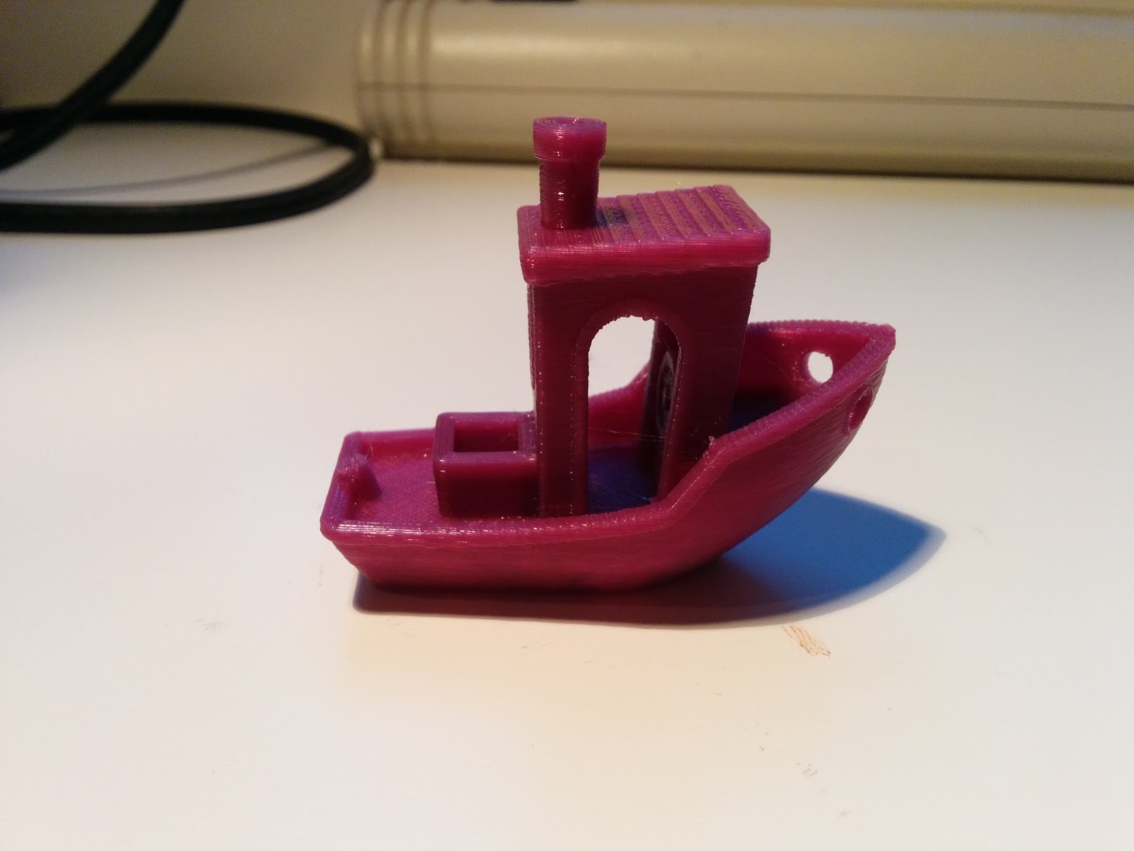
To finish off, here's a gallery of some of the things I printed during these experiments. The yellow boxes are model Google Search Appliances.

Sunday, August 02, 2015

The X/Z Rebuild

Over the weekend, I rebuilt the X/Z axes on my printer using the design by wderoxas, using the STL files here and here. In summary what this does is:

  • move the motors above the frame of the printer, thus reclaiming some vertical space.
  • replace the 5mm threaded rods by 8mm lead screws for smoother and more accurate operation.
  • place a bearing under each motor coupling for support.
  • replace the extruder carriage with one that has four bearings and a better grip on the GT2 belt.
  • replace the X axis end pieces (motor mount and idler) with ones suitable for the lead screws and which also have screws to hold the bearings more tightly.
  • add an X belt tensioner to the idler.
Here are some pictures of some of the parts and the overall construction.


I bought the lead screws and the 608ZZ bearings that go under the motors couplings from Bangood, and the couplings themselves from Folger. I got new LM8UU linear bearings from MakerGeeks.com. They came very oily, unlike the original Folger ones which were quite dry. I also smeared a small amount of white Lithium grease inside them using a q-tip.

I printed all the parts myself. Before taking the printer apart for the rebuild, I checked the prints: were all the holes big enough for the M3s screws, did the bearings fit, did the chrome rods fit, etc. Initially the chrome rods did not fit in the X motor mount, so I reprinted it with a 0.9 extrusion multiplier. The tensioner was too tight in the idler bracket (that's the one on the left), so I sanded it down slightly. I am slightly concerned that they belt rubs on the X carriage as you can see above, so that may need a little sanding down as well. Note that I have used cable ties on the belt, though they are really not necessary, as the teeth mesh and hold the belt quite firmly.

There were a few hairy moments during the rebuild. I first assembled the motors onto the motor mounts and then tried to join everything up, but it was really hard to get things square. In the end my sequence of steps was:
  • assemble the X carriage apart from mounting the extruder. This includes the nuts for the lead screws, but not the lead screws themselves.
  • put it on the vertical chrome rods, loosen the top part of the frame, get it in place, and reattach the top part of the frame loosely.
  • attach the motor mounts without the motors.
  • put the bearings in the motor mounts, then get the lead screws into place.
  • attach the motor couplings and the the motors.
  • gradually get things square and tighten everything up.
Then do the usual setting of the end stops and levelling the bed.

I made two small additional changes. As I mentioned in an earlier post, the end stop brackets that Folger supply are not so great, as the bracket extends some way above the top of the switch PCB. This can cause the switch to never trigger, as whatever is supposed to hit the end switch (the X motor mount specifically) will hit the bracket first. I adapted the bracket to move the holes where the switch attaches up a bit, so the lever of the switch now extends well beyond the top of the bracket. Also, I adapted the X motor mount in blender to add a small cylinder to the bottom of it, into which a M3 bolt can be attached. Then I added a larger plastic head to the bolt, so now I can fine tune the position at which the Z end stop engages without having to move the bracket. It looks like this:


The configuration in Marlin has to be changed to specify new Z steps settings. I thought the pitch was 2mm, which according to this would mean 1600 steps per mm. It was wildly off, and it's because I didn't understand the specification for the lead screws. They have a 2mm pitch but 4 starts, in other words there are 4 intertwined spiral threads. So one turn is actually 8mm, and we want 400 steps per mm, giving this line in Configuration.h: #define DEFAULT_AXIS_STEPS_PER_UNIT   {80,80,400,97.826}

Does it work? Yes! I haven't printed a lot yet, but enough to see that it looks OK. I printed 10mm calibration cubes at 0.3mm, 0.2mm and 0.1mm layer heights, and even at 0.05mm, which I've never managed to do before (with a first layer of 0.15mm to make it stick). The Z movement is very quiet, and the X movement is quieter than it used to be. I also printed a thin walled cube and a few miscellaneous other objects. I can raise the Z position to 150mm, whereas before I could only go to 120mm before worrying the mechanism would tear itself apart. There were are few clunking noises, probably motor skips, and I think I could just have got to 160mm.

Thank you wderoxas for the designs, and also CheopisIV for these pictures of another build.

Tuesday, July 21, 2015

3D: Torturing the Folger 2020 i3.

There are a few "torture tests" for 3D printers out there on the web: objects that are hard to print and expose the qualities and limitations of your printer. Benchy is one, and Makezine published another set of them. Here is what happened when I tried the Makezine set (and you can read about Benchy at the end). They make the STLs available for seven tests and also publish a scoring scheme. It is supposedly objective, although I am less confident of this than they are, and certainly looking at results from other people, there are examples where one looks better than another but the authors used the same score. The comments on the Makezine article include a link to a spreadsheet comparing 23 printers. I have some doubts about the quality of the data. The columns don't correspond exactly to the tests. There is some information that simply cannot be true, in that the Z resonance test requires printing an object 150mm tall, and printers with a maximum height of less than this are recorded as passing the test.

Regardless of these issues, here are my test results. In each case I've given a picture or two, my best guess at the right score, and how many of the printers in the Makezine result did better, equal and worse than this.

All prints are with PLA at 0.2mm layers, 30% infill, using my standard (moderately slow) speed. I've given the time estimates reported by Slic3r. I didn't note the actual times. My printer is a Folger 2020 i3 with a few minor modifications, none of them affecting the mechanical operation.

Unrelated side note: over the weekend, I partially disassembled the Y bed. It's always made a lot of noise, and I was going to take it all the way back to the bearings and put it back together. In the event, I didn't do this. I just saw some of the bolts holding the bearing mounts could be retightened. In some cases, I had never screwed the nylock nuts flush down into the mounts. It's now much quieter. Now it's the X movement that is getting noisy.

1. Dimensional accuracy

The metric here is the diameter of the second largest disc. It should be 20mm in both X and Y. Mine was 19.9mm in X and 19.8mm in Y, giving it a rating of 3. Makezine has 5 better, 8 equal and 10 worse. 43 minutes.

2. Bridging
I'm surprised how well this and the next test worked. Even the longest bridge, 65mm, shows only slight sagging, and it is (I think) in the perimeters. I rate this as either 3 or 4. Assuming 3, which is worse, there are 9 printers better, 3 the same, and 11 worse in the survey. 59 minutes.

3. Overhang
This one is the really amazing test. It prints overhangs at angles ranges from 30 degrees to the vertical to 70 degrees to the vertical.


The Allen key is to hold the piece up, as it doesn't support its own weight. This seems like a 3, as there are some hanging loops on the 70 degree tile, though it isn't far off a 4. 10 better, 4 the same, 9 worse. Better cooling airflow would probably help this and the previous test. 1 hour 28 minutes.

4. Dimensional accuracy
Here you print a block with pegs in it and see which ones can be removed, to see the finest tolerance in the space between the pegs and the block. My first try failed as a peg came loose while the print was still in progress. This is the second try.

I was only able to get the 0.5 and 0.6 pegs out, with a score of 2. 15 printers are better than this, 4 the same, and 4 worse. The print took 42 minutes. The result is consistent with what I've seen on prints with interior holes - they are always too tight. It can be fixed by a lower extrusion multiplier. Maybe less infill would help too.

5. Fine positive space features
Also known as the pointy print.


The thing to look for in this is the fine strands between the points, which gives it a 3. The spires are well formed and quite regular. The strands are an issue I have with my extruder. According to calibration measurements, it does not over extrude, but it does ooze a little before starting the print, and I often get these strands on fast travel moves. One possibility is that the retraction isn't very good. Replacing the extruder is an improvement I'm likely to make one day.

6. Mechanical resonance in XY

This is a pass fail test. I think this is a pass, like 10 of the 23 printers in the test. It took 37 minutes to print.

7. Mechanical resonance in Z
The test object for this is 150mm tall, and that's beyond the capabilities of my printer (though this awesome mod might make it possible). I get nervous when the Z position is above 110mm: I start to hear clunking noises during Z movement. It's probably due to misalignment of the threaded rods, as this would become more apparent closer to the end of the travel when it becomes more mechanically constrained. I decided to do the test with the object scaled down to 100mm. It passes the test conditions in showing no layer registration or ridging problems. In the reported test, 18 printers passed and 5 failed. The print time was 1 hour 9 minutes.

Bonus: Benchy Boat
Benchy is another well known torture test. I did print this once before with fairly good results, but afterwards realized that I was not using the recommended settings, i.e. 0.2mm layers and 10% infill. Here are some pictures from another go with these settings.


I'm really happy with this. There's not even much sagging on the cabin roof, which I did get last time. I won't go through all the analysis listed at http://www.3dbenchy.com/dimensions/. They were all very close except the interior dimensions of some of the round hole. The word 3DBenchy on the stern isn't legible, though you can tell there is something there.

Sunday, July 12, 2015

3D: Some mods, and a rocker switch

I've made a few additions and adjustment to my 3D printer, using parts made on the printer itself.

First, a very trivial change which helped a lot. The Folger kit includes a small plastic loop that attaches to the top of the left hand Z motor to guide the filament. They say attach it to the front outer corner of the motors. Moving it to the back inner corner gives a much straighter path for the filament, and the spool moves more easily as a result. I also printed a small cylinder to act as a spacer between the spool and the frame. If you don't do this, the left hand end of the X carriage rubs against the spool. I haven't seen any evidence of this affecting the prints, but it seems like a bad thing.

I made a mount for the LCD controller which clips to the top of the frame. Here's how it looks:

The model files and another picture are here.

On the extruder, I added a fan shroud which should direct some air to cool the object being printed, using this model. I'm not sure how much difference it makes. I also attached a light as the extruder casts a shadow making it hard to see the details of what is happening. Thingiverse link here, and here is how one version of it looks:
The Thingiverse link describes the electronics. In short, it is three clear LEDs and a 220 ohm resistor, wired to the 12V output of the power supply.

I protected the electronics in a couple of ways. I considered printing a box to put round the electronics. None of the designs I found were quite right, and some didn't print properly, so in the end I made some brackets which can be clipped together into a kind of cage:

Here's the model for this one.

Lastly, I added a cover for the power supply and a power switch:
The cover comes from here, and the power switch box from here. I don't much like this switch cover. It has a single hole for a screw so it's not very solid. I chose it mainly because I had a pack of rocker switches the right size to fit it.

That's all for now. My next project will probably be a rebuild of the Y bed.

Monday, July 06, 2015

3D: Speeding up the Folger

I've written in the past about how the default settings that come with the Folger 2020 are suboptimal and in some cases altogether wrong. One area where I think they can be improved is in the printing speed. Here's some changes I've made. I have only tested them on a simple object, and I've not pushed them as far as they might go for fear of shaking the printer to pieces, overheating the motors, and other scary things. I also only made adjustments to the X and Y values.

According to one of Tom's videos, there are three elements to the speed of the printer:

  • the acceleration. This is said to often be the dominant factor, as it controls how long the printer takes to get up to speed. The Folger config sets this to 1000. Many Prusas uses 3000 or even 9000. I raised it to 3000 in configuration.h, and didn't see any difference.
  • the jerk speed. This tells the printer the maximum instantaneous change in speed it can make before the acceleration parameter has to be considered. I didn't change it.
  • the regular printing speeds. configuration.h has these set to a maximum of 250 mm/s, but the Slic3r configuration sets them a lot lower than this. So these are the values I changed.
My test object is something which is roughly a long thin rectangle about 100mm by 10mm, and I printed it with the long direction along both the X and Y axes. Before making any adjustments, Slic3r estimates it as needing 20 minutes 27 seconds to print. The part of the Slic3r settings to change is Speed, under Print Settings. Folger's values are: perimeter and small perimeter speed 40, infill 50, solid and top solid infill 45, omitting the value I didn't change. I now have them as: perimeter and small perimeter 110, infill 120, solid and top infill 105. The resulting estimated time is 15 minutes 14 second, that is about 75% of the original. In the print about half of layers involve long travel (non-printing) moves without much printing, so it might be even better on other objects.

Thursday, July 02, 2015

3D Printer Project, Part 14: The FolgerTech 2020 Reviewed

Over the last few weeks, I've written a lot about my experiences of buying, building, tuning and using the FolgerTech 2020 3D printer. I'd like now to summarize some of the good and not so good points about this kit. This is not a full review, more like a collection of observations. Up front, I want to say that I think this is a very good kit. I enjoyed putting it together and it gives remarkably good prints. You could of course spend more and get better results, but it is by no means an toy product. You will get a real, working printer out of it.

Some specific good points:
  • the construction is very sturdy. The 2020 aluminium struts are themselves solid and the L brackets that join them together give robust right angle corners without the need for extra bracing. Before I bought the kit, I had some concerns about whether having the Z axis motors at the top or the filament spool on one side would make it unbalanced, and I've not seen any sign of this. I don't have any experience with acrylic framed printers; what I've read and seen on YouTube is that the acrylic is brittle and may warp over team. Acrylic frames were a deal breaker for me when I was deciding what to buy and I was glad to find this kit.
  • the kit was complete. Apart from tools, I had everything I needed. There was one minor error in that the instructions called for one more bolt and nut than the inventory listed. I was able to work round this.
  • the metal parts are cut accurately. All of the 2020 pieces and the chrome rods were the sizes they were supposed to be, to within a millimeter. As I mentioned in my construction diary in previous posts there were only a couple of minor shims and tweaks needed.
  • the printed parts were, in most cases, accurate enough. Everything fitted together the way it should, apart from an issue with the end stops that I'll mention below. Assembling the X carriage took a fair amount of force; this is a good thing, as you want it to be solid.
  • the instructions were pretty good. I never got stuck without an idea of what to do. I know at earlier points in Folger's history people said it was more like they were supplying a kit of parts rather than a kit, and I think this is no longer the case. The same is true of many of the cheap kit vendors. You do have to think for yourself, which for me is fine, as it's part of the point of buying a kit rather than a ready made printer. The weakest points are in the configuration, where some of the information (about Configuration.h) is simply incorrect, as are some of the Slic3r settings.
  • the price. It's about the cheapest RepRap printer kit you can find. The previous points show that they haven't cut corners to make this happen.
  • it an American company. I want to be clear what I mean here. Many people writing on forums and blogs are negative about Chinese vendors. They just assume that Chinese products will be badly made. This has not been my experience of buying things from Chinese vendors (for example via Banggood). The reason I single this point out is that it means fast delivery if you are in the US, and that you can get support from someone in the same timezone and with the same language. It's nice to have that if it turns out you need it. I found Dan from Folger good at replying to my email, and he has also dropped in on the forums at http://forums.reprap.org/ from time to time.
    Edit: I have since heard that Dan has left Folger.
Now a few things that are less good:
  • the ordering process was a bit disorganized. I was given two tracking numbers, one for the printer and one for a spool of filament. The tracking number that was supposed to be for the printer was used for the filament, the one that was supposed to be for the filament was never used, and the printer itself arrived on a third tracking number. Until it arrived, this left me with some doubt about whether the order had even gone through, and I was not able to get Dan to understand this and give me a clear answer.
  • several things show some lack of attention to detail or quality control:
    • as mentioned above, the instructions for configuring the firmware are wrong, and the settings supplied for PLA are wildly out (219C is way too hot). The forums really helped me here, so it turned out OK. Folger should take this information and correct their instructions.
    • one weak spot in the printed parts is the mounts for the end stops. The one I had are such that the level for microswitch on the end stops only just extends beyond the mount. As I described in a previous post, this caused a significant problem for me on the Z axis, resulting in me having to disassemble the X carriage and partly rebuild it. It was fixable, but annoying. No-one else reported this problem, so I may have just got some poor limit switches.
    • the extruder was assembled in a different way to the one assumed by the instructions. Again, this had an easy fix (reversing the extruder motor connection), but it took me a day or two to figure out that this is what was going on.
    • the RAMPS board was so badly made that I didn't want to use it. The soldering quality was awful (again, see an earlier post on this). Dan says they have since switched suppliers, and to his credit, he did offer me a replacement, though in the interests of instant gratification, I had already ordered one from Amazon.
So there we are. If you have any comments on your own experiences with this kit, please add them in the comments, or drop in at the reprap forums (here).

Saturday, June 27, 2015

3D Printer Project, Part 13: Nuts and bolts

Small nuts and bolts seems like an interesting challenge for a 3D printer. You need accuracy in all 3 directions to make sure they are circular and that the threads line up from one layer to another and have the right pitch. I wanted some plastic M3 nuts and bolts to mount the Arduino board without any risk of shorting something. My first attempt, when I was still getting to grips with the printer, was a dismal failure:


It looks like a tiny elephant blowing its trunk. Since then, I've got better at picking temperatures and layer thicknesses and have also made a few physical adjustments.

For printing the bolts, there is a choice between doing them horizontally, in which case they would need some support, and vertically, which I think is better. I was printing 16mm long bolts, meaning the print is tall compared to its base area. Each layer is small, and so this means it does not have much time to cool before the next layer starts. That might be the cause of the wobbles in the earlier example. I tried both 0.1mm layers and 0.05mm with 60% infill in each case. In a previous post, I said I had not succeeded in printing at 0.05mm; this time I did. Here are the results. As you can see they are pretty well straight.


Nuts don't have the same height problem, but as they have very little surface area (they are more hole than doughnut), it is hard to get them to stick. I succeeded in printing a 0.05mm layer version of this. The first attempt at a 0.1mm one detached from the bed and got dragged around by the nozzle. However, adding a 3mm brim in Slic3r solved it. A real metal 3mm bolt went through both nuts, and they also worked with the printed bolts. The metal bolt probably helped clear out the thread. I am not sure I would trust them with a lot of load, but they feel quite firm, and the nut sits squarely on the thread. I also tried a different model. This worked OK, but was a little tighter.

Another question is what to do when you want to print several items. Do you print them one by one, or lay them all out and print them at once? In the latter case, there is more time for each layer to cool before you start the next one, but it also puts more demands on repeatable positioning. I tried this with two bolts and two nuts as a single print. At 0.05mm, I have had no success: I end up with disfigured blobs of plastic which eventually stick to the nozzle. 0.1mm did not do any better. They may be ways round this, such as reducing the print speed or keeping the objects really close together, and for now I am finished with this experiment. Buying nylon nuts and bolts is a better solution for real work, but it's nice to know that if I needed some in a hurry I could make them.