Tuesday, March 29, 2022

Clutch prints

I think this post is mostly directed at my future self, as a reminder of what I did. Here goes anyway.

I have roller blinds in my house made by Mechoshade. They are the sort where you use a metal beaded cord to raise and lower it. Inside the mechanism there is a clutch, between the indented wheel which the cord engages with, and the hex-shaped shaft of the blind itself. The clutch for one of the blinds has failed multiple times. After the original failure, I printed a replacement in PLA:


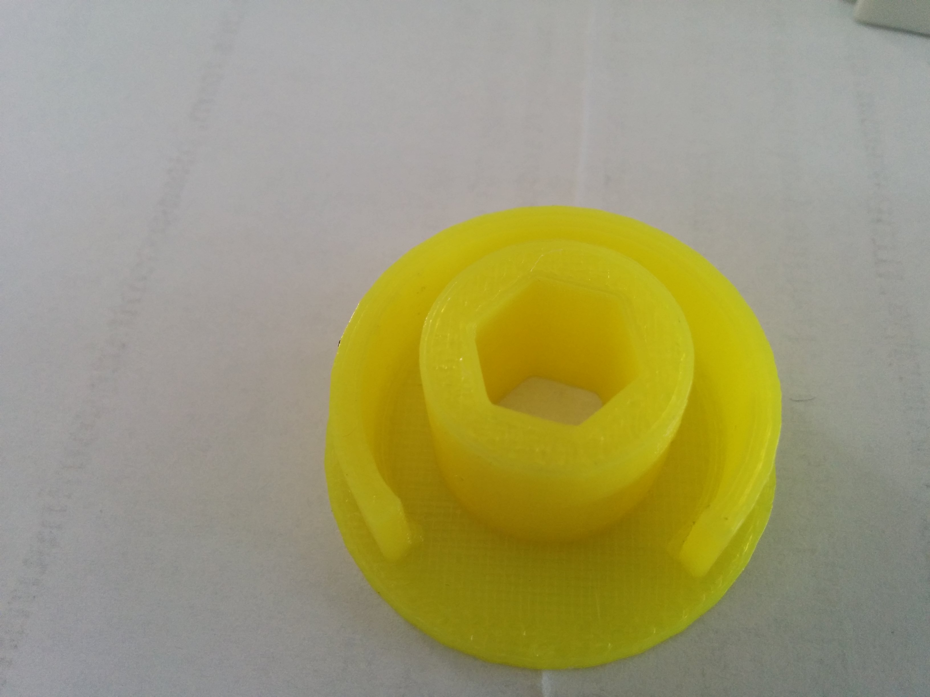
This was in October 2015. I have not tracked how often it has failed since. It's probably two or three times. Usually I print the replacements at 0.2mm layers, 100% infill (if I remember), using PLA. I have tried PETG, which failed immediately. The most recent replacement was a few days ago, and I hope it will hold for a year or two. However, this got me thinking about other materials. Ideally you want something which is strong but not brittle. Strong, because the blind is heavy and I am not always gentle with the cord. Brittle materials tend to fail suddenly after multiple stress cycles, which seems likely to be the case here. PLA has the strength, but is also brittle. PETG didn't work because it is not very strong. A chart on Taulman's web pages gives a good guide to the material characteristics. I decided to look at nylon and two related filaments.

For Nylon itself, I bought a 200g roll from Gizmodorks. I didn't note the exact print settings I used. The results were not great. A first attempt had a poor finish with blobs all over the surface. I think this was at 250. A second attempt with a lower temperature had a better finish but the print delaminated. It is possible that the filament had not been kept well. Nylon is hygroscopic and some sites say that even a few hours exposure to the air will make it damp enough to cause problems. The print surface was blue tape with glue stick. Blue tape on its own was not enough, and when using an unknown filament I prefer not to use PEI sheets so as not to risk damaging them.


Next, I tried Taulman PCTPE. As I understand it, this is a mixture of nylon and a flexible filament similar to TPU. I used it once before, a long time ago, to make a headphone holder and found it to be very strong. For the print settings, I started with one of the flexible filament profiles in PrusaSlicer, and increased the volumetric flow rate to 5mm^3/s. Initial attempts on blue tape warped. Blue tape with glue stick worked. I also started with 240/50 and then reduced it to 220/50 for the successful print. You can hear bubbles popping a higher temperature and see water vapor coming off it. The result is quite flexible, possibly too much for the clutch.

Finally, I tried Taulman 910. This is supposed to be very strong under tension, while still having some flexibility. Some people say it is hard to print with and needs a high temperature and an enclosure. For met it worked fine at 240/50 on blue tape with no need for glue stick. The result is a little more flexible than I expected. It definitely feels strong; I have no way of evaluating this more precisely.

Warped PCTPE:


PCTPE and 910:


(Sorry for the poor pics. My camera was having difficulty focussing.)

I have not fitted the new clutches yet. It's a nuisance to take the blind apart so I'll wait until it fails again. This might not be for a year or two.

Tuesday, March 22, 2022

Favre's Clock 24

Jacques Favre has designed several interesting clocks, the designs for which are available on myminifactory. I built his Clock 24 design. It is weight driven, and uses a Graham escapement. The run time when it is mounted at a reasonable height (5 feet or so) is about 24 hours. This could be increased by using doubling the weight cord through a pulley.


One striking thing about Clock 24 compared to all of the others that I've made is that it is huge. The scape wheel and largest gears are almost twice the diameter of the ones in the first Peterson clock and the frame is corresponding larger. It uses arbors of 5mm and 2mm diameter, compared to 3mm and 1.5mm in the Peterson clock. I'm not sure of the consequences of this for ease of getting it going. I think it probably makes it a little less sensitive to printing tolerances. Does it make it more or less sensitive to friction? The contact area with the arbors is larger (more friction) but bears less force per unit area (less friction). I just don't know. As with previous clocks, I used brass rods for the arbors as it's easy to cut them without power tools.

I found it quite easy to get going after a made a few small adjustments; mostly adding some extra washers to keep some of the gears clear of each other. There are a few variants for the design, the most interesting being in the mechanism which goes between then main gear train (known as the going train) and the winding gear (which carries the weight). This can either be two gears with a simple ratchet, or a more complex design with a spring to act as a power reserve for the going train during winding. I elected to go with the simpler option. The escape wheel also has two variants, one with full depth teeth and one with tapered teeth which may have lower friction. I started with the tapered version, but found that the anchor tended to wobble as it only has a small area of contact with the escape wheel teeth. The non-tapered version worked better.

One interesting design choice is the clutch. In the Peterson clock, this is done by a spring which holds a gear and a spacer in contact. The Clayton Boyer design that I built uses a small pad of leather held against the arbor with set screw. Favre's clutch sandwiches the arbor between two metal rods with screws to adjust how tightly it is held. I didn't take a picture before assembling the clock but perhaps you can see it here:

Or perhaps not.

I am still testing the clock. I have the timing quite well tuned now. The weight is about 1.3kg; less might work.  As I write this, it has been running for a bit over 12 hours continuously. A couple of previous runs stopped after 1-2 hours and it seems that something was binding. Some of the previous clocks have stopped when friction has consumed too much of the power of the clock. You see the pendulum losing more and more of it swing and finally dropping below the amount needed to engage with the escape wheel. When Clock 24 stopped, it seemed more like something in the gear train had locked up, and it took a nudge to free it and get things going. It may be that the gear can't move freely enough on the arbors (not enough endshake maybe). If it binds again, I'll see if I can get a better idea of what is going on.

Thursday, March 03, 2022

Two minor clock projects and an update

I recently completed a couple of new clocks, both brief experiments.

Neopixel clock

The first uses a circular array of WS2812 LEDs, sometimes known as neopixels. It's hard to take good pictures of it, as the brightness of the LEDs overwhelms the camera on my phone. This will give a general idea:


The LEDs are this product. It consists of several concentric rings which different numbers of pixels. It's a nice, cheap product and comes with connectors so that you can use just some of the rings and address them in any order. The only alternative I found was an overpriced product from Adafuit.

The outermost ring has 60, making it suitable for minutes and seconds, and the next has 48, meaning you can displays hours down to quarter-hour resolution. I use the next ring, with 40 pixels for a temperature display, although that part of the software is not complete. The controller is a M5StickC Plus. Strictly speaking a level shifter should be used between the 3.3V output of the ESP32 in the M5, and the 5V needed for the control pin of the pixels, but it seemed to work OK without one. The only problem I had was during prototyping when I had it connected up through leads with alligator clips. For some reason, the signals got corrupted in this case. Using a breadboard or soldered connections works fine. The hours and minutes are displayed as a sort of swoosh with several LEDs at different brightnesses. The case is 3D printed in clear PLA. This does make the pixels a bit fuzzy, though most of the fuzziness in the video is from the camera.

The neopixel clock is not very practical. It's surprisingly hard to read the time without hands to direct your eye. I hoped the swooshes would help, but they really don't: every time I look at it, it takes a few seconds to read off the time, when it ought to be near-instantaneous.

Favre's Full Clock

The second recent build is Jacques Favre's "full clock". It's a straightforward clock mechanism driven by a small stepper motor, the widely used 28BYJ48. I used the ULN8003 driver board that came with the one I bought instead of the L293D preferred by Favre. The clock needs two 608 bearings, and there are printable versions. I had several 608s in stock, so used them instead.


The clock runs silently and smoothly. I like this design better than Steve Peterson's stepper clock (see this post), which is not quite as quiet and slightly jouncy in its movement. One concern is whether the 28BYJ48 will stand up to continuous running as they aren't really designed for it.

I am thinking of making some of Favre's other clocks, and this short project was meant as a way of learning more about his design style. Almost all of the parts worked fine. The only modifications I made were to shrink two parts with an inner thread by 95% for a better fit, and to make the hands a bit less boxy. There are some shafts glued together from two halves and I made 1mm diameter holes in them so I could use a pin or piece of wire to keep them aligned while the glue set.

Peterson 10 day clock update

Steve Peterson's 10 day clock was the first one I made. One problem I have had with it is that after a few weeks of running, the pendulum amplitude gets less and less until it stalls. Reading the comments thread on his myminifactory page, this is a problem which several people have had. The proposed solution is always to find ways of reducing friction, and I have been through several cycles of doing so: re-cleaning the bearings, polishing the arbors, reprinting the gears in regular PLA instead of silk PLA, lubricating with white lithium grease. I also tried adding more weight. The pattern has been the same every time: it seems good at first, but after 4-6 weeks of use, the problem recurs. I'm now trying ceramic bearings to again try to bring down the friction. We'll see what happens.