Last time, I wrote about the design considerations for a clock adapted from William Strutt's epicyclic gear clock. Now it is time to complete the design by adding the frame and the driving/timing mechanism. There is one small change I made to the design documented in the previous post. The planet gear is mounted on a carrier pivoted on the minute arbor. This works better if you add a counterweight opposite the planet gear. A US quarter seems to be about right.
A few pictures and video of the completed design first, and then I'll fill in a few details.
The Frame
The frame for Strutt's original design (illustrated here) is rather ornate and a little too fancy for my tastes. I like the frame seen on a GrabCAD version and used this as the starting point for my own. The overall frame has to be taller than will fit on the print bed. In previous designs, I've looked for a point where I can split the frame and then joined the pieces with glue and pins. For my design, I decided to print it so that the very top part attaches with a couple of screws. This also allowed me to defer the decision about the drive and timing mechanism. Depending on what I decided, I could print the top pieces with different dimensions.
Drive and Timing
Most of the remaining design decisions concerned the drive and timing mechanism, that is how to get power into the clock and how to make it run at the right rate. The original clock used a spring, but I was not sure the plastic design would hold up to the stresses from it. Another option was to drive it with a weight attached to the minute arbor. The works OK for a wall mounted clock, but is not suitable for a desk clock. I toyed with using a stepper motor, but again did not like this. In the end I settled on the same drive as my two previous clocks: an electromagnetic pendulum. As before, the pendulum rotates a cam, causing pawls to engage with a toothed wheel. I'll call it an escape wheel, though this might not be an accurate use of terminology. The escape wheel then drives the ring gear via a pinion.
There are several design considerations. The number of teeth on the pinion and escape wheel must be chosen to drive the ring gear at the right rate; details of the calculations are in the previous post. The period of the escape wheel then determines the length of the pendulum, which must be less than the height of the frame at the pivot point of the cam. Finally, the teeth on the escape wheel must be large enough for the pawl to engage with it reliably. I considered reusing the exact escape wheel dimensions from one of the previous designs, but the escape wheel looks large and out of proportion. A smaller escape wheel is possible, but it must then have fewer teeth so that they are a reasonable size. After some playing around I decided on an escape wheel about 80mm in diameter with 40 teeth, with an 8 tooth pinion. This is about the smallest size of pinion that I was willing to trust. I used a trick I learned from Steve Peterson for the pinion. As only one face comes into contact with the ring gear, you can fatten up the teeth and make them stronger by displacing the trailing face.
With the gears I chose before, the ring must rotate once every 754.49 seconds, and the escape wheel then rotates each 8/168*754.49 = 35.928 seconds. Each complete swing on the pendulum advances it by one tooth, so the time per swing of the pendulum is 35.928/40 = 0.8982 seconds. An ideal pendulum for this period would then be almost exactly 200mm long, which fits well with the size of the frame.
Cam and pawl dimensions
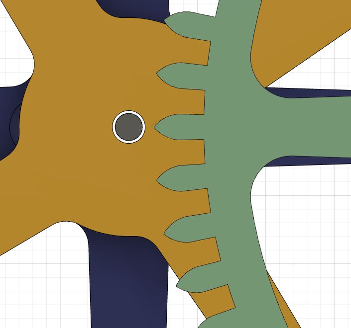
I'll come back to the pendulum design in a moment, but first there is the question of how to design the cam and pawls given the escape wheel. A reason for wanting to reuse the previous designs is that I knew they worked. Unlike designs for standard escapements (such as the Graham escapement), I couldn't find any guidelines for working out the geometry. To solve this, I set up a sketch in Fusion 360 to try to make sure it would all work. Here is an annotated version:
Circle A represents the circle at the base of the teeth, B is the pivot point of the cam, and C and D are the pivot points of the driving pawl at the limits of the pendulum's motion. p and q are the points where the end of the pawl would contact the teeth. The angles of lines BC and BD are set by how far the pendulum swings. Experiments with the previous clocks suggest it is about 20 degrees. We can freely choose most of the other dimensions: the escape wheel diameter, the position of the cam pivot, the length of the cam, and the length of the pawl (Cp and Dq). I could then measure the angle between the pawl position at the extreme ends of the pendulum swing: the angle between the radii to p and q. This must be more than the angle between two teeth, 9 degrees for a 40 tooth wheel, but less than the angle between two teeth, as we don't want to advance the wheel too far. Based on this, I was able to choose dimensions which appeared to work, and validated them with a quick and incomplete print.
The pendulum
I mentioned that an ideal pendulum would be 200mm long. The actual pendulum for this clock deviates from ideal in multiple ways. The period calculation for a pendulum assumes the angle through which is swings is small (a few degrees), while the electromagnetic pendulum in this clock swings by something like 30 degrees. Secondly, in the ideal case, there is a mass just at the end of the pendulum. We have to have the magnet at the end, and the position of this is fixed so that it is close to the drive coil. To make it possible to adjust the timing, there is also a moveable weight bob. In the last two design, I made the pendulum shaft from a brass rod. The weight bob was held in place with a set screw, making fine adjustment tricky. This time round, I printed the pendulum shaft with a thread cut in it, and made both the weight bob and magnet holder similarly threaded. Adjustment is then much easier, and a lock nut can be used to hold the weight bob in position once the timing has been set. The weight bob is just a small printed part with a couple of M5 bolts attached to it. There are two 12mm x 3mm neodymium magnets.
The electronic circuit is the one I described a while back. It is controlled by an Arduino Nano, and this has the nice property that the code can measure the pendulum period and report it over the Nanon's serial connection. The electronics enclosure is a bodge, with various things held in place with blue tape and an opening for the USB port which is far too large. It's held to the frame with a rather flimsy bracket. One day I will come back and do this properly. Maybe.
The pendulum moved very vigorously - so much so that the frame rocks slightly. If I did a redesign, I would make it a bit heavier. The clock is very quiet compared to the two other electromagnetic clocks.
Wrap up
This is my eighth clock and the first one I have designed entirely, other than drawing the initial inspiration and (initially) the gear ratios from Strutt's original. I went though multiple iterations both in silico with Fusion 360 and in the printed parts. It's a cliche to post a picture of your box of rejected parts, so I won't. I'm happy with the end result.
In the early 1800s, William Strutt designed a clock based on an epicyclic gear train. There is a good description of it in an edition of the Horological Times. The key elements of the gear train are shown in the following illustration. The frame, escape wheel and driving force are omitted.
To understand how this works, start from the minute arbor. It is attached rigidly to the planet carrier (white). As the carrier revolves, it moves the planet gear (green). The blue gear is one of two sun gears and is fixed to the frame (not shown). The movement of the planet gear has two effects. Firstly, it turns the ring gear (red). At the top, you can just see a small pinion (also green), which would be attached to the escape wheel. This therefore regulates the time. The period of the escapement and the gear ratios are chosen so that the planet carrier rotates once per hour, as required for the minute arbor. The final element is the hour gear (yellow). It is also a sun gear, and is free to rotate on the minute arbor. It has the same diameter but a different number of teeth is different to the fixed sun gear. This is an implementation of Ferguson's mechanical paradox. The rotation of the planet gear causes the free sun to rotate at 1/12th of the rate of planet around the fixed sun, providing the rotation for the hour hand.
There are some existing designs based on Strutt's original, for example one by Clayton Boyer, one by Brian Law (without the paradox), and at two on GrabCad (1, 2).
The gear ratios work as follows. Let:
A = teeth on fixed sun gear
B = teeth on planet pinion
C = teeth on planet gear
D = teeth on inner side of ring gear
E = teeth on outer side of ring gear
F = teeth on escape pinion
G = teeth on escape wheel (not shown)
H = teeth on free (hour) sun gear
The period of the planet carrier (and hence the minute arbor) divided by the period of the ring gear is 1+AC/BD. The period of the escape wheel divided by the period of the ring gear is F/E. We'll come back to the hour gear in a moment.
In Strutt's design, A=66, B=8, C=68, D=144, E=168, F=6, G=34 and H=72. Thus, if the period of the planet carrier is 3600 seconds, the period of the ring gear is 3600/(1+(66*68)/(8*144)) = 735.3 seconds, and the period of the escape wheel is 735.3*6/168 = 26.26 seconds. As there are 34 teeth on the escape wheel, the period of the pendulum must be 26.26/34 = 0.772 seconds, implying the pendulum is about 14.8 cm (5.8 inches) long. This makes the mechanism suitable for a desk clock, as in the example shown in the Horological Times article.
I don't fully understand how the Ferguson's paradox works, but I can give some hand-waving reasoning about why it gives the right timing. Essentially, each turn of the planet about the fixed sun (66 teeth) advances the free sun by its number of teeth, 72. This turn takes one hour, so in that time, the free sun has advanced by 72-66=6 teeth relative to the fixed sun. This is 1/12th of its total number of teeth, hence making it rotate once every 12 hours. Note that in order for the free sun to have the same diameter as the fixed sun, it must have a different module (ratio of diameter to number of teeth), thus breaking the normal rule for gears to engage correctly.
Design decisions for a 3D printed version
I wanted to take this design and adapt it for 3D printing. The hardest part of this is finding a size which will work, by picking a suitable module for the gears. This then constrains almost everything else. We need to be able to print both a very small gear (escape pinion, 6 teeth) and to fit a very large one (ring gear, 168 outer teeth) on the print bed.
There is one other constraint. The tips of the planet gear teeth must not come too close to the minute arbor:
The distance from the center of the minute arbor to the tip of the planet gear teeth is (A+B-C-2)m/2, where m is the gear module. This follows from the center of the planet and planet pinion being (A+B)m/2 from the center, and the outer radius of the planet gear being (C+2)m/2.
At a module of 1.2, the ring gear is 204mm in diameter, and will just fit on the bed of a Prusa MK3S. The escape pinion is tiny at this modulus, with an outer diameter of just 9.6mm and teeth only about 1mm across. We actually do have some freedom to use a larger planet pinion, which in turn changes the size of the pendulum. For example, with 10 teeth (and hence 12 mm diameter), the pendulum needs to be 41cm long. You can somewhat compensate by adding more teeth to the escapement wheel: if we change it from 34 to 40 teeth, the pendulum needs to be about 30cm for a 10-tooth pinion.
The spacing between the axis and the tip of the planet gear teeth is 2.4mm, meaning the minute arbor diameter must be under 4.8mm in a world where everything is perfectly sized. In practice, you have slightly more leeway as the printer will round off the very tips of the teeth, but you also need to allow for slight misalignments and wobble as the mechanism moves. There is one further issue associated with this. The free sun (shown in yellow) is loose on the minute arbor, so seen from the side it looks like this:
In this illustration, the minute arbor diameter is 2mm, about as small as possible. How do we keep the free sun in its position along the shaft? One option is to add a shaft collar just underneath it, rigidly attached to the shaft. Another would be to add a spacer, but its hard to find a diameter which can both be printed reliably and won't interfere with the planet gear. We could also use a piece of thin tube as a bushing; for example, a 2.5mm tube with a wall thickness of 0.225mm.
Another possibility is to reduce the number of teeth in the planet gear. At 66 teeth, we have 3.6mm radial space instead of 2.4. At 64 teeth, we have 4.8mm space. The number of teeth on the inner side of the ring gear must decrease to compensate, and the pendulum needs to be slightly longer. Making this change in no way alters the Ferguson's paradox, as it is only the fixed and free suns and the planet pinion which participate in this. With 64 teeth, there is no need for a shaft collar and instead the planet carrier can be modified:
It is possible to use a 3mm minute arbor in this configuration. The inner ring gear now has 140 teeth and a slightly longer rotational period. With the 6/34 escapement, the pendulum would need to be about 1 cm longer than before.
Tooth profiles
Most gears use an involute tooth profile: the classic shape with a narrowed "waist". Cycloidal gears are an alternative that has been used in clocks, and it works well for 3D printing as the teeth have straight sides with no waist. Once the teeth are above a certain size, the sides are parallel and so fewer small gap fill movements are required from the printer. For small teeth, the sides are not parallel, though it is possible to adjust a bit from the strict profile to avoid them becoming too fragile. Fusion 360 and Blender both have add-in gear generators, but they only work for involute teeth. I was able to find a cycloidal gear generator as downloadable software. There is an online version as well, but I prefer the downloadable version as it can generate SVG files, which are more convenient for converting into sketched in Fusion 360. The SVGs need to be scaled to the correct size after loading them up. One thing the software lacks is a way of generating the inner teeth for the ring gear. Some people suggest creating an outer gear and then using it to cut away the inner part. It is approximately correct for involute teeth, but does not work for cycloidal ones. My approach was to load the SVG file, then flip the lines making up one tooth about a chord drawn on the pitch circle:
Another problem with the output of the gear generator is that the arcs at the base of the teeth do no quite line up with the edges of the teeth. I solved this by adding a base circle to the teeth. To generate the gear in Fusion 360, I extruded one tooth, copied it with a circular pattern and then added the body of the gear using the base circle.
Drive and timing
Strutt's design used a pinion plus escape wheel for the timing and was driven by a spring coupled to the minute arbor. You could also drive the minute arbor with a weight, if the clock is configured as a wall clock. The gears move quite freely and so could also be driven by a stepper motor in a similar way to Steve Peterson's desk clock. Another option is to use an electromagnetic pendulum. I can't find any examples of exactly this, though there is a somewhat related design by Nigel Climpson.
Prototype
I wanted to validate that the basic mechanism works before going further. It's a bit hard to video it (not enough hands!), but this clip shows that it moves quite smoothly.
If you look carefully, you can see the hour wheel advancing. For the next stage, I need to settle on the drive mechanism. The planet carrier also needs a slight redesign so that the circular piece counterbalances the planet gear.