Last time, I wrote about the design considerations for a clock adapted from William Strutt's epicyclic gear clock. Now it is time to complete the design by adding the frame and the driving/timing mechanism. There is one small change I made to the design documented in the previous post. The planet gear is mounted on a carrier pivoted on the minute arbor. This works better if you add a counterweight opposite the planet gear. A US quarter seems to be about right.
A few pictures and video of the completed design first, and then I'll fill in a few details.
The Frame
The frame for Strutt's original design (illustrated here) is rather ornate and a little too fancy for my tastes. I like the frame seen on a GrabCAD version and used this as the starting point for my own. The overall frame has to be taller than will fit on the print bed. In previous designs, I've looked for a point where I can split the frame and then joined the pieces with glue and pins. For my design, I decided to print it so that the very top part attaches with a couple of screws. This also allowed me to defer the decision about the drive and timing mechanism. Depending on what I decided, I could print the top pieces with different dimensions.
Drive and Timing
Most of the remaining design decisions concerned the drive and timing mechanism, that is how to get power into the clock and how to make it run at the right rate. The original clock used a spring, but I was not sure the plastic design would hold up to the stresses from it. Another option was to drive it with a weight attached to the minute arbor. The works OK for a wall mounted clock, but is not suitable for a desk clock. I toyed with using a stepper motor, but again did not like this. In the end I settled on the same drive as my two previous clocks: an electromagnetic pendulum. As before, the pendulum rotates a cam, causing pawls to engage with a toothed wheel. I'll call it an escape wheel, though this might not be an accurate use of terminology. The escape wheel then drives the ring gear via a pinion.
There are several design considerations. The number of teeth on the pinion and escape wheel must be chosen to drive the ring gear at the right rate; details of the calculations are in the previous post. The period of the escape wheel then determines the length of the pendulum, which must be less than the height of the frame at the pivot point of the cam. Finally, the teeth on the escape wheel must be large enough for the pawl to engage with it reliably. I considered reusing the exact escape wheel dimensions from one of the previous designs, but the escape wheel looks large and out of proportion. A smaller escape wheel is possible, but it must then have fewer teeth so that they are a reasonable size. After some playing around I decided on an escape wheel about 80mm in diameter with 40 teeth, with an 8 tooth pinion. This is about the smallest size of pinion that I was willing to trust. I used a trick I learned from Steve Peterson for the pinion. As only one face comes into contact with the ring gear, you can fatten up the teeth and make them stronger by displacing the trailing face.
With the gears I chose before, the ring must rotate once every 754.49 seconds, and the escape wheel then rotates each 8/168*754.49 = 35.928 seconds. Each complete swing on the pendulum advances it by one tooth, so the time per swing of the pendulum is 35.928/40 = 0.8982 seconds. An ideal pendulum for this period would then be almost exactly 200mm long, which fits well with the size of the frame.
Cam and pawl dimensions
I'll come back to the pendulum design in a moment, but first there is the question of how to design the cam and pawls given the escape wheel. A reason for wanting to reuse the previous designs is that I knew they worked. Unlike designs for standard escapements (such as the Graham escapement), I couldn't find any guidelines for working out the geometry. To solve this, I set up a sketch in Fusion 360 to try to make sure it would all work. Here is an annotated version:
Circle A represents the circle at the base of the teeth, B is the pivot point of the cam, and C and D are the pivot points of the driving pawl at the limits of the pendulum's motion. p and q are the points where the end of the pawl would contact the teeth. The angles of lines BC and BD are set by how far the pendulum swings. Experiments with the previous clocks suggest it is about 20 degrees. We can freely choose most of the other dimensions: the escape wheel diameter, the position of the cam pivot, the length of the cam, and the length of the pawl (Cp and Dq). I could then measure the angle between the pawl position at the extreme ends of the pendulum swing: the angle between the radii to p and q. This must be more than the angle between two teeth, 9 degrees for a 40 tooth wheel, but less than the angle between two teeth, as we don't want to advance the wheel too far. Based on this, I was able to choose dimensions which appeared to work, and validated them with a quick and incomplete print.
The pendulum
I mentioned that an ideal pendulum would be 200mm long. The actual pendulum for this clock deviates from ideal in multiple ways. The period calculation for a pendulum assumes the angle through which is swings is small (a few degrees), while the electromagnetic pendulum in this clock swings by something like 30 degrees. Secondly, in the ideal case, there is a mass just at the end of the pendulum. We have to have the magnet at the end, and the position of this is fixed so that it is close to the drive coil. To make it possible to adjust the timing, there is also a moveable weight bob. In the last two design, I made the pendulum shaft from a brass rod. The weight bob was held in place with a set screw, making fine adjustment tricky. This time round, I printed the pendulum shaft with a thread cut in it, and made both the weight bob and magnet holder similarly threaded. Adjustment is then much easier, and a lock nut can be used to hold the weight bob in position once the timing has been set. The weight bob is just a small printed part with a couple of M5 bolts attached to it. There are two 12mm x 3mm neodymium magnets.
The electronic circuit is the one I described a while back. It is controlled by an Arduino Nano, and this has the nice property that the code can measure the pendulum period and report it over the Nanon's serial connection. The electronics enclosure is a bodge, with various things held in place with blue tape and an opening for the USB port which is far too large. It's held to the frame with a rather flimsy bracket. One day I will come back and do this properly. Maybe.
The pendulum moved very vigorously - so much so that the frame rocks slightly. If I did a redesign, I would make it a bit heavier. The clock is very quiet compared to the two other electromagnetic clocks.
Wrap up
This is my eighth clock and the first one I have designed entirely, other than drawing the initial inspiration and (initially) the gear ratios from Strutt's original. I went though multiple iterations both in silico with Fusion 360 and in the printed parts. It's a cliche to post a picture of your box of rejected parts, so I won't. I'm happy with the end result.
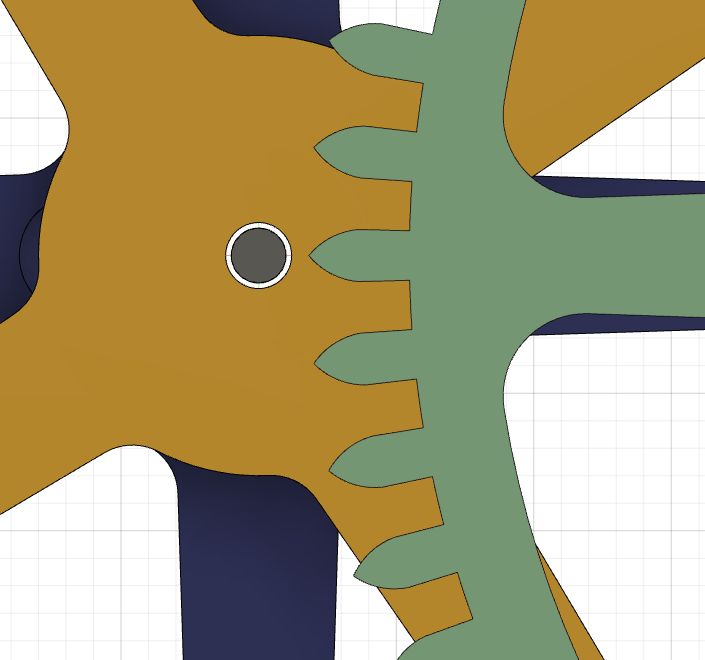
In the early 1800s, William Strutt designed a clock based on an epicyclic gear train. There is a good description of it in an edition of the Horological Times. The key elements of the gear train are shown in the following illustration. The frame, escape wheel and driving force are omitted.
To understand how this works, start from the minute arbor. It is attached rigidly to the planet carrier (white). As the carrier revolves, it moves the planet gear (green). The blue gear is one of two sun gears and is fixed to the frame (not shown). The movement of the planet gear has two effects. Firstly, it turns the ring gear (red). At the top, you can just see a small pinion (also green), which would be attached to the escape wheel. This therefore regulates the time. The period of the escapement and the gear ratios are chosen so that the planet carrier rotates once per hour, as required for the minute arbor. The final element is the hour gear (yellow). It is also a sun gear, and is free to rotate on the minute arbor. It has the same diameter but a different number of teeth is different to the fixed sun gear. This is an implementation of Ferguson's mechanical paradox. The rotation of the planet gear causes the free sun to rotate at 1/12th of the rate of planet around the fixed sun, providing the rotation for the hour hand.
There are some existing designs based on Strutt's original, for example one by Clayton Boyer, one by Brian Law (without the paradox), and at two on GrabCad (1, 2).
The gear ratios work as follows. Let:
A = teeth on fixed sun gear
B = teeth on planet pinion
C = teeth on planet gear
D = teeth on inner side of ring gear
E = teeth on outer side of ring gear
F = teeth on escape pinion
G = teeth on escape wheel (not shown)
H = teeth on free (hour) sun gear
The period of the planet carrier (and hence the minute arbor) divided by the period of the ring gear is 1+AC/BD. The period of the escape wheel divided by the period of the ring gear is F/E. We'll come back to the hour gear in a moment.
In Strutt's design, A=66, B=8, C=68, D=144, E=168, F=6, G=34 and H=72. Thus, if the period of the planet carrier is 3600 seconds, the period of the ring gear is 3600/(1+(66*68)/(8*144)) = 735.3 seconds, and the period of the escape wheel is 735.3*6/168 = 26.26 seconds. As there are 34 teeth on the escape wheel, the period of the pendulum must be 26.26/34 = 0.772 seconds, implying the pendulum is about 14.8 cm (5.8 inches) long. This makes the mechanism suitable for a desk clock, as in the example shown in the Horological Times article.
I don't fully understand how the Ferguson's paradox works, but I can give some hand-waving reasoning about why it gives the right timing. Essentially, each turn of the planet about the fixed sun (66 teeth) advances the free sun by its number of teeth, 72. This turn takes one hour, so in that time, the free sun has advanced by 72-66=6 teeth relative to the fixed sun. This is 1/12th of its total number of teeth, hence making it rotate once every 12 hours. Note that in order for the free sun to have the same diameter as the fixed sun, it must have a different module (ratio of diameter to number of teeth), thus breaking the normal rule for gears to engage correctly.
Design decisions for a 3D printed version
I wanted to take this design and adapt it for 3D printing. The hardest part of this is finding a size which will work, by picking a suitable module for the gears. This then constrains almost everything else. We need to be able to print both a very small gear (escape pinion, 6 teeth) and to fit a very large one (ring gear, 168 outer teeth) on the print bed.
There is one other constraint. The tips of the planet gear teeth must not come too close to the minute arbor:
The distance from the center of the minute arbor to the tip of the planet gear teeth is (A+B-C-2)m/2, where m is the gear module. This follows from the center of the planet and planet pinion being (A+B)m/2 from the center, and the outer radius of the planet gear being (C+2)m/2.
At a module of 1.2, the ring gear is 204mm in diameter, and will just fit on the bed of a Prusa MK3S. The escape pinion is tiny at this modulus, with an outer diameter of just 9.6mm and teeth only about 1mm across. We actually do have some freedom to use a larger planet pinion, which in turn changes the size of the pendulum. For example, with 10 teeth (and hence 12 mm diameter), the pendulum needs to be 41cm long. You can somewhat compensate by adding more teeth to the escapement wheel: if we change it from 34 to 40 teeth, the pendulum needs to be about 30cm for a 10-tooth pinion.
The spacing between the axis and the tip of the planet gear teeth is 2.4mm, meaning the minute arbor diameter must be under 4.8mm in a world where everything is perfectly sized. In practice, you have slightly more leeway as the printer will round off the very tips of the teeth, but you also need to allow for slight misalignments and wobble as the mechanism moves. There is one further issue associated with this. The free sun (shown in yellow) is loose on the minute arbor, so seen from the side it looks like this:
In this illustration, the minute arbor diameter is 2mm, about as small as possible. How do we keep the free sun in its position along the shaft? One option is to add a shaft collar just underneath it, rigidly attached to the shaft. Another would be to add a spacer, but its hard to find a diameter which can both be printed reliably and won't interfere with the planet gear. We could also use a piece of thin tube as a bushing; for example, a 2.5mm tube with a wall thickness of 0.225mm.
Another possibility is to reduce the number of teeth in the planet gear. At 66 teeth, we have 3.6mm radial space instead of 2.4. At 64 teeth, we have 4.8mm space. The number of teeth on the inner side of the ring gear must decrease to compensate, and the pendulum needs to be slightly longer. Making this change in no way alters the Ferguson's paradox, as it is only the fixed and free suns and the planet pinion which participate in this. With 64 teeth, there is no need for a shaft collar and instead the planet carrier can be modified:
It is possible to use a 3mm minute arbor in this configuration. The inner ring gear now has 140 teeth and a slightly longer rotational period. With the 6/34 escapement, the pendulum would need to be about 1 cm longer than before.
Tooth profiles
Most gears use an involute tooth profile: the classic shape with a narrowed "waist". Cycloidal gears are an alternative that has been used in clocks, and it works well for 3D printing as the teeth have straight sides with no waist. Once the teeth are above a certain size, the sides are parallel and so fewer small gap fill movements are required from the printer. For small teeth, the sides are not parallel, though it is possible to adjust a bit from the strict profile to avoid them becoming too fragile. Fusion 360 and Blender both have add-in gear generators, but they only work for involute teeth. I was able to find a cycloidal gear generator as downloadable software. There is an online version as well, but I prefer the downloadable version as it can generate SVG files, which are more convenient for converting into sketched in Fusion 360. The SVGs need to be scaled to the correct size after loading them up. One thing the software lacks is a way of generating the inner teeth for the ring gear. Some people suggest creating an outer gear and then using it to cut away the inner part. It is approximately correct for involute teeth, but does not work for cycloidal ones. My approach was to load the SVG file, then flip the lines making up one tooth about a chord drawn on the pitch circle:
Another problem with the output of the gear generator is that the arcs at the base of the teeth do no quite line up with the edges of the teeth. I solved this by adding a base circle to the teeth. To generate the gear in Fusion 360, I extruded one tooth, copied it with a circular pattern and then added the body of the gear using the base circle.
Drive and timing
Strutt's design used a pinion plus escape wheel for the timing and was driven by a spring coupled to the minute arbor. You could also drive the minute arbor with a weight, if the clock is configured as a wall clock. The gears move quite freely and so could also be driven by a stepper motor in a similar way to Steve Peterson's desk clock. Another option is to use an electromagnetic pendulum. I can't find any examples of exactly this, though there is a somewhat related design by Nigel Climpson.
Prototype
I wanted to validate that the basic mechanism works before going further. It's a bit hard to video it (not enough hands!), but this clip shows that it moves quite smoothly.
If you look carefully, you can see the hour wheel advancing. For the next stage, I need to settle on the drive mechanism. The planet carrier also needs a slight redesign so that the circular piece counterbalances the planet gear.
Fusion 360 has tools for creating involute gears, including its own spur gear add-in and GfGearGenerator, and they work well. However, if you want cycloidal gears, it's not so easy to find something that works. Here's one approach, in case this turns out to be helpful to anyone else.
Start by generating the gear in DXF form using Rainer Hessmer's Cycloidal Gear Builder. Make sure to use the highest quality level. It's useful to include a hole in the middle so you can identify the center. Download the DXF file. If you load this DXF into Fusion 360 (Design > Insert > Insert DXF) you will get an unhelpful error message. The DXF file isn't in a form that Fusion 360 can handle and we need to fix it.
You can fix the DXF by importing into FreeCad and then exporting it again. Another option is to import it to Inkscape and save it with "Save As". The DXF should then import into Fusion 360. However, if the gear is large, Fusion 360 may sit for hours processing it. It might never finish. Selecting "One sketch per layer" when inserting it sometimes helps, but generally does not. So another option is save it as a SVG from Inkscape and insert that instead. It's still slow, but does work. If you are lucky, you might be able to extrude the result and create the gear from it. Or sometime Fusion 360 will just abruptly exit.
The Cycloidal Gear Generator is supposed to have an option to output to SVG but it was missing when I looked for it. However, instead you can download a desktop version of the app from here. This will give you a SVG with much better segments. Note that you have to specify that you want a pinion. In the web version you can omit it. The desktop version raises an exception if you try. The result will load into Fusion 360, but it won't work as the segments don't join into a closed curve. However, we can use the sketch as a starting point.
First note that the imported SVG won't have the right size. We need to scale it. To find the scale factor measure an element of known size. For example, if you created a 6mm hole in the middle of the gear, measure its actual diameter and scale by 6 divided by this. Measuring the radius is usually easiest, and so then you would scale by 3 divided by the measurement. To scale the whole sketch, exit sketch mode, go to Modify>Scale, select the sketch from the browse list, and enter this factor.
Now we want to go into edit sketch and delete everything except for the center hole and one tooth. The tooth will consist of two lines and two arcs. You ought to be able to create a circular pattern with these and the arc joining them to the base of the next tooth, but you don't get a closed path if you do. The problem is that the exact end points of the lines aren't right. So change everything to a construction line (with x), then change the two lines and two arcs back. Create a center circle with circumference on the ends of the lines. Now create a circular pattern with the two lines and the two arcs about the center of the gear, with a number of elements equal to the number of teeth you want. You should now be able to exit sketch mode, select all the teeth and the circle you just created, and extrude your gear.
One of the designs in the book Making Wooden Gear Clocks is for an electromagnetic gear clock driven by a simple and baffling mechanism. I took the design and adapted it for 3D printing; as with some of the other clocks, I won't publish my design as the copyright status is unclear. Here is the clock:
The clock works as follows. The pendulum is driven electromagnetically by means of a magnet in the end of the pendulum and a coil in the base. The coil detects when the magnet comes close and then sends a pulse to drive it on its way. The pendulum drives a cam with two pawls on it. This in turn engages with a toothed wheel and advances it once per second. The principles thus far are similar to the Thriecan clock described in a previous post.
The minute wheel is also a toothed wheel, with the opposite orientation to the seconds wheel. A small metal rod near the middle of the seconds wheel engages with the teeth of the minute wheel and advances it once per minute.
There is also a pawl for the minute wheel to prevent it falling back. The minute wheel is tightly attached to an arbor which also carries the minute hand.
Now we get to how the motion of the minute wheel is divided down 12:1 to the hours motion. This is done by means of the daisy wheel. The daisy (or daisy wheel) motion was invented around 1830 by Aaron Dodd Crane. The wooden clocks book does not credit the invention or explain how it works. There is a little more information in Philip Woodward's book My Own Right Time.
The daisy wheel has 11 petals and 11 notches between the petals. A device ("tri") with 3 arms interacts with the daisy wheel by means of pins mounted on the ends of the arms. A rod attached to the daisy holds it loosely in place in the frame, allowing this movement while preventing it from just rotating with the tri. Woodward mentions that the number of arms and pins is not critical. The hour hand is mounted on the tri. The key to this is that some parts of the mechanism are mounted eccentrically to the minute arbor and so the whole system operates in a manner similar to epicyclic gears. I will have more to say about that eccentric mounting in a moment, but first I want to say that I simply do not understand this in any detail. Every time I try to reason it through, my brain breaks. The explanation in Woodward and in another work as well as several YouTube videos do not make it any clearer to be and mostly they end up with a statement along the lines of "you have to see it to believe it". It clearly does work. I just can't understand how, and why having 11 notches on the daisy leads to a 12:1 reduction.
I've been a little evasive about exactly what is eccentric, and the reason for this is that I think the design in Making Wooden Gear Clocks is incorrect. In the design as shown in exploded form in the book, on the accompanying plans, and in the photos showing it being assembled, the daisy is mounted co-axially on the minute arbor. A part called the tri excentric in the book is also mounted on the arbor, such that its axis of rotation is offset from the axis of the minute arbor. The tri rotates about this offset axis. Thus the parts look like this:
The daisy therefore stays stationary while the tri and hence the hour hand rotate around an axis which is not coincident with the minute axis. As a consequence the hour hand moves off-center to the minute hand. You can see this in the following video, in which I turn the minute wheel by hand.
I have not been able to find any video of other builds of this clock which show it running for more than a few seconds, which is not long enough to see the problem. Consulting Woodward, Shelley's book on Crane, and several YouTube videos (example 1, example 2, example 3) show that this design is simply wrong. The tri and hour hand should rotate on the same axis as the minute arbor. To quote from Woodward:
the daisy wheel is mounted loosely on an eccentric collar rigidly fixed on the central arbor of the clock.
It is the daisy that should be eccentric to this axis, and although the daisy does not rotate, it does move a little to accommodate this motion. It's hard to believe that the author of the design and the editors of the book failed to notice this. As far as I can tell, they have not acknowledged the error or published any errata for the book.
After initially building the clock according to the published design, I reworked the daisy and tri to the correct configuration. Here is how the hour hand motion looks now:
The reworked parts look like this:
As with some of the earlier clocks, I view this as a clock demonstrator rather than a practical timepiece. I wanted to see how the mechanism worked. For this reason, I didn't spend a lot of time on the frame and base. I quite like the minimalistic "candlestick" design. I thought it might be too unstable, but it seems OK.
I used my own electronics in this clock, detailed in an earlier post. One unexpected issue I had was this: the clock was working fine when I had it attached to a piece of plywood for testing. Then when I mounted it on its base, the pendulum became very unstable. It would jump all over the place. This turned out to be because the magnet was attracted to the screws in the corner of the case and to the USB connector. I solved this by using weaker magnets and moving them a little lower to compensate.
In a previous post, I described some experiments with circuits for driving an electromagnetic pendulum. The results were not very satisfactory, and for the Thriecan clock, I ended up using a commercial module. I have since revisited this, and now have something I am happier with. To recap: the pendulum contains a magnet. As it approaches the center of its swing, a sensor detects its presence, and then energizes a driver coil to impart some momentum to the pendulum. Ideally, you use one coil as both the sensor and driver. The circuit I present here uses an Arduino and a small number of discrete components.
Some initial experiments
In the first attempt, I was unable to get a strong signal from a coil: only a few millivolts. This is probably because of the geometry of the coil, which had a narrow diameter but was quite long (about 25mm), based on the one in the instructions for the Toucan clock. It is better to have a shorter, fatter coil, so that more of the winding is close to the magnet as it passes by. I rewound the coil on a bobbin with a 6mm inner diameter and a length of 10mm. I did not count the number of turns or measure the length of wire. Based on its resistance (35 ohms) and the resistance per unit length for 32 AWG magnet wire, it is around 60m. The winding is about 30mm in diameter.
I wanted to know how much difference the specific magnet made, so I constructed a pendulum with the magnet on the end of a 300mm brass rod and measured the voltage when the pendulum was dropped from a known position. The magnets I had lying around were:
20mm x 4mm N38
12mm x 3mm N35 (I think)
12mm x 3mm N42
10mm x 3mm N52
All but the first gave about 0.3V. If you add a second or third one, this goes up by 0.1V per additional magnet. The 20mm one gave 0.5V or around 0.65V with two. I was a bit surprised that the grade of magnet didn't make a difference, as each unit of N rating is supposed to correspond to an extra 1% in magnetic field strength (or something like this).
The distance between the magnet and the coil also makes a difference. My test setup didn't allow me to change it much, but an increase of distance between the coil and the magnet from about 3mm to about 6mm dropped the voltage by half.
The circuit
Here is the circuit. I'll explain the ideas behind it in a moment.
(Diode: 1N4001. Transistor: PN2907.)
The voltages I measured aren't enough to register as a digital signal when connected to an Arduino and are maybe too low to switch a transistor which could be attached to a digital input. An alternative is to use an analog input of the Arduino and then set a threshold in code based on the analog reading. With a resolution of about 5mv per step, we should be able to do this. A reading of even 0.1V would be detected as a value change of 20 on the analog input.
If you search the web for advice on connecting a coil as a sensor to an Arduino, there is a lot of unclear (and possibly misleading) information. The main concern is that transients from the coil could exceed the input voltage range of the Arduino and so damage it. Various solutions involving voltage dividers or Zener diodes can be found. I don't think this is necessary. The Arduino inputs have protection diodes which limit the voltage to just above 5V and just below 0V. The issue with the protection diodes is that they can only handle a limited amount of current. 1mA might be OK, 100uA definitely is. More than that would likely burn them out. In the circuit above, the flyback diode on the coil should eliminate most of the risks, but to be sure, I designed the circuit to allow for a 10V swing. In this case, with a 100k resistor on the analog input, the current would be 100uA and we are OK. Relying on the protection diodes is something that people argue about on various forums, leading to some of the other solutions. An application note from Atmel has an example in which an analog pin is connected safely to mains at 110-240V AC. Also take a look at this.
There is one further issue with using the analog input. The Arduino datasheet recommends that the input impedance to analog pins should be 10k or less, and we want to use 100k. Looking into this in more detail, the reason appears to be that the analog to digital converter works by charging a capacitor internally and them sampling its voltage. The internal capacitor is 14pF and it should be charged in 6us or less at standard sampling rates. With a 100k external resistor, we have a time constant of 1.4us, so we should be OK.
The remaining input element is the 10uF capacitor. It largely gets rid of noise and ringing on the input without slowing down the signal too much. Looking at the signal on an oscilloscope, there is still a small and short duration spike at an acceptable level. With no capacitor at all, there are spikes for about ten milliseconds before the circuit settles down.
On the output side, we simply drive a transistor from a digital pin. When the pin is low, the transistor turns on and the coil is energized. The sensor can't be read at the same time, and that's OK as we don't need to. The flyback diode helps to protect the transistor when it turns off and the field in the coil collapses.
In previous experiments, I found that I needed external power to get enough drive in the coil, mainly due to use a coil with less good geometry. For this version, the 5V output of the Arduino worked fine. Its Vin can also be used if a higher voltage or current is needed. I experimented with an Arduino Uno, but will move to using a Nano soon.
The code is similar to the version I gave before, namely:
read the sensor
when it exceeds a threshold (20), wait (10ms)
turn on the coil (200ms)
turn off the coil, and wait a little longer (10ms)
keep going
I still have to tune the exact timings and the threshold. These values give a very strong swing to the pendulum. Currently I am not using a weight bob or tuning to 1s per cycle, and this may affect the timing and possibly the voltage needed to drive the coil.
I've not fitted this to the Thriecan clock. My intention is to use it for a possible future design.
The Thriecan Clock is a modified version of Clayton Boyer's Toucan clock, adapted for 3D printing. The key feature of this clock is a electromagnetic pendulum. There is a magnet attached to the end of the pendulum and a coil hidden in the base. As well as providing the timing, the pendulum also provides the energy to drive the clock. As the pendulum approaches the vertical position, the electronics attached to the coil senses the magnet and applies a pulse to the coil. This pushes the magnet and hence the pendulum away and the process continues. The top of the pendulum is attached to an arbor and this turns a cam with two pawls. One pawl, called the pick-up pawl, pushes on the escape wheel. The other pawl then holds the escape in place while the pick-up pawl moves back for the next cycle. The remainder of the clock is a standard gear train to divide the rotation of the escape wheel down to minutes and hours.
The version you see here is not quite final. I am going to replace the battery pack with power connector so I can connect it or a different power source. There is enough room to locate the battery pack in the base, but it disrupts the operation by attracting the pendulum. There's also a few screws sticking out while I make final adjustments and I will then replace them with shorter ones.
Adapting the design
The original design was intended to be made out of wood. You can see many examples on the Toucan clocks YouTube channel. I bought a copy of the plans in DXF format and loaded them up into Fusion 360 to provide a starting point for the sketches. For parts where the dimensions were critical, I used these sketches directly, and for others I either adapted them (for example, the cam) or replaced them entirely (for example the weight bob). The original design used 3/8 inch arbors, and I replaced these with 3mm ones. Instead of printing separate gears, connectors and pinions and then gluing them together, I merged them into a single part. This is something which works nicely for 3D printing, but it difficult or impossible in woodwork. I undersized many of the holes for the arbors and for the pendulum shaft and drilled them out to either a tight fit or a loose one. I've not always been successful in getting good tight fits and so where possible I also provided holes for set screws.
One of the hardest parts to adapt was the frame. It is much too big to fit on the printer bed. It's possible to split up large pieces like this and then glue or otherwise connect them. However, I didn't like where the splits ended up so I changed the shape of the frame. It still needs to be split into three pieces: the main part of it, the left foot, and the curve reaching down to the right foot. You lose the nice curve on the left hand side of the original design by doing this. The joins are hidden behind the dial on the left and where the arc on the right joins the vertical part. In each case, as well as gluing the parts, there are some metal pins joining them. These help keep the parts aligned while the glue sets and provide a little extra strength. The dial is also slightly smaller, and has a central bar to help support one arbor and the hour wheel. It's held on to the frame with two M3 screws. I didn't really think ahead here, so I ended up having to use 45mm screws with a bit of padding behind the frame to get the length just right.
One reason for wanting to try this specific design was to see how easy it is to start with a plan designed for woodworking and adapt it for 3D printing. It worked out somewhat well. The process was a bit hindered by the ways the plans are supplied: the DXF is a single gigantic file some parts of which are actual plans, and some parts of which are descriptive text, assembly diagrams and other auxiliary information. It seems an odd way of doing things. Fusion 360 gets a bit heated when you load all this in, and so a fair amount of initial pruning was needed. I'm also a novice with Fusion 360, so the way I did some things might not be best.
The pendulum
The pendulum is a 2mm brass rod with the magnet holder as the bottom and the weight bob around the 25cm mark. Adjusting the position of the weight is a bit fiddly as it involves loosening the screw underneath it, and sliding it up or down. The bob holds quite tightly to the shaft so adjustment can be down without tightening the screw until it is in its final position. The weight itself is a few M3 screws in the shiny little bucket.
The pendulum is connected to the cam with a 3mm brass shaft. This is a problematic part of the design, as the weight of the pendulum is greater than that of the cam and pawls, causing the shaft to tilt to the back. There are a few ways this could be fixed; perhaps a counterweight on the front, or a longer support glued to the back of the frame. Another option would be to move everything in front of the from forward and lengthen the shaft. For now, it works OK as it is.
One tooth or two?
Looking at the examples of the Toucan clock on YouTube, there are two different philosophies about the position of the pick-up pawl and the stop pawl at the point where the pick-up pawl starts to push on the escape wheel. They can either be on adjacent teeth like this, or separated by one tooth like this. The clock runs either way, and you can set the way it works by adjusting the angle between the pendulum and the cam. It may make some difference to the required swing of the pendulum. Looking at the first 10 videos on the YouTube list, I saw 8 were adjacent (the Toucan closes its beak) and 2 were separated (the Toucan eats with its mouth open). I went for adjacent, which sets the cam a bit anticlockwise from the pendulum.
Driving circuit
I experimented with various driving circuits. As mentioned in a previous post, I had no success with getting a 1 or 2 transistor circuit to work, and after fiddling around for a long time, I wasn't happy with any of the other options I tried. In the end, I decided to buy a ready made module from carveshop. It works well, but is a little pricy. I plan to spend some more time looking into this, in part because I have a second electromagnetic pendulum clock I would like to try.
For a future clock project, I would like to construct an electromagnetic pendulum. The pendulum has a magnet at its tip, and base contains a coil of thin wire. We aim to detect when the pendulum is approaching, and then turn on the coil for a short time to add extra energy. This can be done by turning on the coil to attract the magnet before the pendulum reaches the center (vertical), or waiting until it has passed the center and turning on the coil to repel it.
There are many different ways of doing this, and it was used in commercial clocks before electronic movements took over. The German-made Kundo clocks are one example. If you look on the web, you will find many articles about electronic pendulums, whether for clocks or just as toys, with a variety of different circuits. One of the best descriptions is Kundo battery clocks by Rod Elliot, with several possible circuits and a lucid explanation of how they each work. There is a 2 coil, 1 transistor design, used in Clayton Boyer's Toucan clock, and two variants of a 1 coil, 2 transistor design from the Kundo clocks themselves. In another article on the same site, Rod Elliot notes that there is some trial and error in getting these circuits going. After playing around for a few days without getting to anything reliable, I agree. I also found a site with a very similar circuit and a comment thread full on people saying how they never managed to get it to work. I'm not sure why I had so much difficulty. I know that for a few components (capacitors mainly), I didn't have the exact values and had to come up with a substitute. I tried out several different coils that I had around. Some didn't produce enough voltage to turn on the transistors. They would need more turns or more cross-sectional area, both of which affect the induce voltage. Others could clearly turn on the transistors but didn't impart enough energy the the pendulum.
There are other solutions, both analog or digital. One analog option is to replace the transistors with two or more stages of op-amps. You can then tune the sensitivity of the triggering better, and also add some delay before the pulse to the coil happens. Other solutions use a simple microprocessor like a PIC, or a TI chip.
I decided to go with a simple and highly controllable solution. I had some KY003 Hall effect sensor boards in my stock of parts, and so I just connected one to an input pin on an Arduino. The Arduino can't drive the coil directly, so I hooked up an output pin to a transistor, like this:
The transistor is a PN2222, and the Arduino output pin connects to the 22k resistor.
The code is quite simple:
wait until the Hall effect sensor turns on.
wait a while to allow the pendulum to reach the center.
energize the coil for a while.
check the Hall effect sensor has turned off (in case we are still within range).
The pendulum itself if a 30cm brass rod. I want a period of about 1 second, so there is a weight around 25cm from the pivot. The magnet is at the end. The delay after detecting the sensor should be long enough for the pendulum to reach or just pass the center. If the angle of the pendulum at its extreme is P, and the angle at which we detect the sensor is S, then the delay should be arccos(S/P)/6.28, to a first approximation. The 6.28 comes from the angular frequency being 6.28 radians/second for a 1 second pendulum. See here. None of this is exactly right, as it assumes a small angle for P, whereas I actually see around 20 degrees in each direction. It also does not allow for extra energy being added to the system. But it will do to get roughly the right values.
This is the prototype working. It needs a small nudge to get going:
Here's the code. Note this is a prototype and might change before the final version.
// Electromagnetic pendulum controller.//// Detect the magnet with hall effect sensor on this pin...
constexpr int hall_sensor =3;
// ... then wait this many milliseconds ...
constexpr int detect_to_activate_delay =23;
// ... then energise this output pin ...
constexpr int output =7;
// ... for this many milliseconds ...
constexpr int activation_duration =200;
// ... with this much slop in milliseconds when checking the sensor is out of range.
constexpr int sensor_cooldown =10;
// Use this pin for LED.
constexpr int led =13;
voidsetup()
{
pinMode(led, OUTPUT);
pinMode(output, OUTPUT);
pinMode(hall_sensor, INPUT);
digitalWrite(led, LOW);
digitalWrite(output, LOW);
}
voidloop()
{
// Sensor reports LOW on detecting a magnetic field.if (digitalRead(hall_sensor) == LOW) {
delay(detect_to_activate_delay);
digitalWrite(output, HIGH);
digitalWrite(led, HIGH);
delay(activation_duration);
digitalWrite(output, LOW);
digitalWrite(led, LOW);
// Wait until the magnet is out of range of the hall effect sensor, and then allow a little longer.while (digitalRead(hall_sensor) == LOW) {}
delay(sensor_cooldown);
}
}
Additional notes
After some experimenting with this form of drive, I think there are some good and bad points.
Good points: it is very easy to build as the circuit is so simple. It's convenient for tuning the timing. You can add a few extra lines to report the time between ticks. Note that the activation delay and duration make very little difference to the timing, so this is about adjusting the position of the bob on the pendulum.
Not so good: getting both the Hall effect sensor and the coil close enough to the magnet is a challenge. I mounted the sensor on top of the coil, but this then requires a large coil to supply enough impulse. The force on the magnet goes down (if I remember correctly) as the square of the distance from the coil. To make life easy, my coil was whatever was left on a 4oz could of 30AWG magnet wire, probably about 300 metres. Anything much less than this didn't work. This could be solved by more careful design, such as mounting the probe embedded in the top of the coil or in the hole in the middle.
I recently downloaded some DXFs originally designed for use with a CNC machine, with a view to converting them into something suitable for 3D printing. Blender is my go-to for quick manipulations, but in this case I wanted some more advanced tooling and so I decided to use Fusion 360. I had multiple problems, and so I decided to document them here in case this helps others in the same situation. The root cause of most of the problems is disconnected segments. It seems that some programs which output DXFs will leave a small gap between segments. As a result Fusion 360 can't find closed curves and this prevents it doing many important operations such as extruding. The DXF file I am working with is about 4MB and contains around 30 separate items, some for parts such as gears, and a few to illustrate how the parts fit together. I'm only interested in the former. I also tried cutting one part from the sketch into a new sketch for some tests.
You can recognize when there are broken segments if extrude and similar operations are not available, or if you hover over what looks like a closed curve and it does not all highlight. Generally you have to zoom in a long way before you can find the segments that are not joined. If there were only a few of these, fixing them by hand would not be too much of a burden, but when you have each gear has two or four of these per tooth, it quickly becomes time consuming.
A first thing to note is that Fusion 360 has two ways of importing DXFs. In both cases, the result is one or more sketches. The options are:
From the Design > Insert menu, there is an Insert DXF function. It seems to be essential to set this to "One sketch per layer" to avoid it taking a very long time. In the file I was working with there were 9 layers.
Use the DXF Import Add-in, from the Fusion 360 App Store. I was hopeful about this, as it includes an option to fix the sketch by joining close elements, either on import or as a separate operation. The fixing stage appears to be extremely expensive. I tried importing the large file with the fix option turned on, and after several hours it was still going. I doubt that it would complete in a reasonable time, as by that point Fusion 360 was using around 7GB of RAM, forcing my PC to continually swap and so grind to a halt. With the smaller sketch, I didn't run up against the memory limit, but the fixing stage simply didn't do anything. Note that the Add-in does not allow you to set the units (DXF files don't specify what units they are in), a curious omission.
I then looked at other scripts and add-in designed to fix cases like this. I found three:
ConnectTheDots is a Python script. The example video shows it working on exactly the case I wanted. It operates on the selected part of sketch, which I though might allow me to concentrate on just the parts I was interested in. Unfortunately, the script does not work with current versions of Fusion 360. It raises a Python exception. It appears to be unmaintained.
ConnectTheDots (another one) is a fork of the original version. It does not raise an exception, but never seems to complete.
FillGaps is a paid add-in. It costs $10. There is a free preview version to try it out, though the preview is not very useful as you can't examine the resulting segments. It can join nearby disconnected points by either adding a new segment or merging them. It doesn't take a huge amount of memory, though it can be quite heavy on CPU. It works on the whole of a sketch. Unfortunately, on my large test file it got slower and slower. At the start, the progress bar (which shows percentages) advanced by 1% every 10-15 seconds. From 99% to 100% took multiple minutes, and it then stayed at 100% for an hour and a half until I cancelled it. On the small sketch (cut and paste of a single gear), it finished quickly and accurately. So this looks like a good option, with the inconvenience of having to do a lot of cutting and pasting.
One other option is to load the DXF into blender, select a part from it, convert it to a mesh and then use Blender's Edit Mode operation to combine vertices by distance. This works, but leaves the result as a mesh and in some cases seemed to add some distortion. You can also only export meshes as DXF from Blender and not curves: if you try to export as a curve, then it silently does nothing. However, if you want to continue doing all your modeling in Blender it might work.
A final possibility is to treat the DXF as not being part of the model at all, and just use it to guide creating new sketches with them a guidelines. This isn't great for complex geometry such as gears, but could be combined with the Fusion 360 gear generator add-in to generate gears matching the ones in the DXF.
The clock consists of a stepper motor driving a gear train to turn the seconds, minutes and hour hands. One of the arbors, called the "gear 5 arbor" and located at the top right, has two gears held together by friction. There is a spring clutch just behind the larger gear. This allows you to turn the knob at the back to adjust the time. The clock is driven by an Arduino Nano and a NEMA 17 motor. Normally a Nano would not have enough power to drive a NEMA 17, but in this case an uncommon type with a higher coil resistance and lower current requirements is used. There is an intermediate board designed and sold by Steve Peterson which simply connects five ports of the Nano to each coil of the motor. Each port is connected through a resistor, with values which are approximately in powers of two. The control program can then advance motor with 1/32 microstepping. The circuit has a passing resemblance to a resistor ladder DAC, though it is not quite the same. It's quiet and works well, with low power requirements and minimal circuitry.
A few places in the mechanical part of the clock rely on parts being a tight fit on their arbors. I'm not keen on this approach. With 3D printing, you have to undersize the hole and then hope to drill it out to a suitable diameter, then force the part into the right position. I found all of the parts were already too large for the arbors. The holes have a diameter of about 1.65mm and fit onto 1.5mm shafts. With some printers and filament, the hole might close up enough to make this work. For me it did not. I decided in the end to print the parts with a small transverse hole and hold them in place with M1.5x5 screws. One piece where I did this is the gear 5 insert that holds the spring for the clutch in place. It needed some care to avoid the screw interfering with the large gear at the back (gear 2, in the design). I also found that you have to be careful in attaching the knob on the back of arbor 5, used to adjust the time. If it drags on the back of the frame at all, this is enough to stop the minute and hours hands.
The stepper runs quite smoothly, but when it is attached to the gear train, there is noticeable judder. In testing, I started with just gear 2 and saw a lot of rebound on each step. It gets less as you put the rest of the gear train together. The following video illustrates:
I used Mika 3D silk PLA throughout. The gears are so-called rose gold, which is in fact a pale pink. The frame is silk black, which is more like a dark grey. I'm not all that pleased with the appearance. Either a darker black or a bright color would have made for better contrast on the numerals. Two of the parts (the stepper gear and the smaller gear on arbor 5) warped during printing, like this:
I was surprised by this. It used to happen a lot when I had a poor quality printer and used blue tape as the print surface. I have not had it happen at all since I got the Prusa MK3. The parts were OK on reprinting them.
With the code as downloaded the clock was accurate to within 2 seconds over an hour. I am tuning it further by tweaking the parameters in the code.
And a small update
The first clock in this series, also by Steve Peterson, had been working quite well and accurately for several weeks until recently. It now occasionally stops and the pendulum swing is less than it used to be. I am intending to add a bit more weight to the weight shell, but also think I probably need to take it apart and check for anything that might have slipped out of alignment, particularly on the pendulum arbor.
With all that I've written recently about 3D printed clocks, I thought I should not neglect a purely electronic one. Some while back I bought a M5Stack. It's a packaged ESP32 with a screen and (in this model) some neopixel LEDs. I wrote code to use this as a clock. It periodically resyncs to a reference time if it has a wifi connection and otherwise tracks the time internally. This variant of the M5Stack doesn't have a real time clock, but there is a library for tracking the time without one. The colored LEDs on the side very gradually change color: a color encoded as HSV is picked at random and the color change until it reaches the target value. It can run off the internal battery or from USB power. Here's a few minutes of it, at 30x speed:
Brian Law is a British designer of clocks. Most of his designs are intended to be made out of wood, and he sells plans for them on his site, woodenclocks.co.uk. He has also adapted a few of the designs for 3D printing. There is a simple beginner's design, and three designs which are more interesting mechanically. I decided to make his Clock 27 design. This is a weight driven clock with a pendulum, and the interesting feature of it is that is uses a novel escapement, designed to minimize friction. A blog post explains how the escapement works. I like the design and found it fairly easy to get it running, with only a few issues. I do think there are a few ways in which it can be improved to make it easier to print and assemble. I'll come back to these in a moment, but first some pictures and video:
The clock running:
And in slow-mo. Make sure you have the sound on for this.
When I first assembled the clock, it would run for a few seconds (20 was the longest) before stopping. The pendulum was not swinging enough to keep the clock going. I tracked this down to the gravity arm, the piece on the left shaped like a crescent moon. The blog post says that "The finger on the end of the Gravity arm needs to be adjusted so that it causes the trigger to release the Escapement wheel just before the fork in the fork in the Lifting lever [The L shaped piece] reaches the curved tooth", and this was not happening. As a test, I stuck a small piece of plastic on the tip of the gravity arm. The clock then ran, though a bit unevenly. I reprinted the gravity arm with the tip extended by 1mm, and took the chance to check over and clean up all of the remaining parts, and after that it ran smoothly.
Brian Law has several parts that are to be printed separately and glued together. For his version, he used ABS, and there are plenty of effective solvent glues for it. I used PLA, where the only glue that works well is gel cyanoacrylate. It requires the surfaces to be smooth and quite close fitting for the glue to hold. One case where it is suggested is to assemble parts like this:
There are two gears here, the big 60 tooth one and the smaller 15 tooth one. They are printed separately because of the overhang and then joined into a single piece. A single part this shape would otherwise need support to print. I found the parts did not glue well together as there is a fairly large gap around the mating piece (which is part of the upper gear). One way of improving this would be to make it a tighter fit. A better way would be to make the mating piece and the hole it goes into hexagonal. And best of all is to extend the teeth of the upper gear down and then merge the pieces into a one that can be printing as a single entity, like this:
This is the solution I adopted. I did glue some of the pieces as recommended, for example the wall spacers on the back of the frame, but also found a few more places where it was easy to modify and then merge the parts.
The clock relies on some of the gears being tight on their shafts, and the design undersizes some of the holes so they can be carefully drilled out to fit the arbors. In most cases, you could get away with a looser fit and extra spacers as an alternative. The one place where there has to be a tight fit is the 60T gear which mates which the ratchet. It directly drives the shaft it is on and thereby the minute hand. I found it was too loose at first, and so tightened the interior hole as well as adding a couple of hole for M2 set screws. This seemed to work; even without the set screws the fit was tight enough that I had to tap the rod with a small hammer until it was in place and the screws are only there in case it loosens up over time.
Note that there is an error in the bill of materials for the clock. Instead of needing three 100mm shafts and one 69mm one, it actually needs one 100mm and three 70.5mm; similarly, you need one 31mm shaft, not three. I used several different materials: stainless for the 100mm, carbon steel (McMaster Carr High Tolerance Rod) for two of the 70.5mm rods, and brass for the remaining one. This was based purely on what I had available. Brass is my preference as I can cut it with hand tools, unlike stainless, and it doesn't corrode. The carbon steel corrodes a little, and as I live near the ocean this can become a problem over time.
A few of the parts are on flying shafts (I mean ones which are only held at one end). Law suggests adding a magnet to keep them in place. I prefer a simpler solution: make the shafts slightly longer and print a tight fitting cap for them. Take a look at the second picture above for some examples.
One other issue I encountered is that once you have attached the dial to the frame, two of the screws which hold the front of the frame to the back are inaccessible.
Before I modified the gravity arm the beat was very patchy and I worried that this might be due to uneven teeth on the gears. However, once I made the slightly longer gravity arm, it ran evenly. It has met my basic test (running for 1 hour). I have yet to tune the timing and as you can see in the pictures it is still mounted on a test frame rather than on the wall.
Where next?
This is the fourth clock I've made recently, each based on a slightly different principle: hanging pendulum, seesaw pendulum, balance wheel, gravity escapement. It's not that I especially love clocks, more that I just find it interesting to make them and then get them working, and I enjoy finding complex printing projects. There's a few more designs I will probably try out. I don't leave most of them running: if I want to tell the time, there are plenty of much more accurate electronic devices within easy reach. The only one that I do leave going all the time is the Peterson clock, in part because it runs for 7 or so days without rewinding. It has stalled a couple of time in the last few days after a few weeks of working well, so some maintenance might be needed.
A footnote
A day after posting the above, I moved the clock from the testing frame to a permanent position on the side of a bookcase, and found it didn't run for more than about 45 seconds. I think this is just that it was not balanced. It took a while, but after slowly adjusting the angle it was hanging at and also adding a washer to the gravity arm to give it a bit more momentum, it seems to be running better - at least two hours without stopping.
It is, of course, well known that everybody loves string, except when you are 3D printing. In the clocks that I've made recently, there is often a lot of stringing between gear teeth which are close together. It doesn't take much to clean it up: a few gentle swipes with a piece of sandpaper generally does the trick. However, there's always some residue left behind. The common advice is to lower the printing temperature, so I did a quick check to see if this helps. I selected a gear with 18 teeth, printed it at different temperatures and counted how many of the gaps between the teeth had significant stringing. "Significant" is a bit subjective here; roughly, I mean I would feel obliged to clean it up. Here's the results:
You probably can't make out too much in this picture. The counts of stringy teeth were:
210C: 10
205C: 10 or 11
200C: 4 to 6
195C: 3
190C: 3
So this validates that a lower temperature helps. 210C is the Prusa default for PLA and I think they use it to ensure a good flow. I'll certainly consider lower temperatures in future.
One of the oldest clock designs on thingiverse is this model by user TheGoofy. It has many makes and several remixes. I made this once before several years ago, and never got it to run reliably. At the time, I had a printer which was much less accurate and well-tuned than my current one. TheGoofy notes in his description that it was designed for older, more inaccurate printers. I think that I couldn't make it work as a combination of what my printer was able to produce and my ability to figure out what was going wrong and fix it.
I recently had another go, with some success. Here are some pictures and video:
The video was taken while I was still tuning it, and it's quite obvious that the beat and timing are off. Here is a later version that is a bit better:
It worked pretty much straight off with only a few changes. Some of the parts came out undersized. In most cases this does not matter, but in the pentagonal connector between the escapement spring and the balance wheel, it is important to get a good fit. The original spring is 1mm thick, and I found that the coils flopped around too much. I found a remix with a 1.3mm spring. The end of the spring has a triangular piece which fits into the frame, and this was also far too loose. At first I held it in place with some tape, and then adjusted the model to make a tighter fit. One other adaptation I needed was to drill out the holes for the arbors in all the gears and moving parts, as they were too tight. My preferred way of doing this is with a drill bit in a pin vise. It allows you to go slowly and carefully control the drill so that you don't end up skewing the hole.
I used the v1 ratchet and no planetary drum. This gives the shortest running time in the sense that the weight falls a greater distance for a given run time. As I was regarding this a more of a clock demonstrator rather than something I intend to use as a real timepiece, I didn't worry about this too much. I like the idea of the servo driven version, and may try it out later. I found that the clock ran quite reliably with 600g of weight. I think 500g is also OK, but less than that wasn't enough. Note that TheGoofy recommends 1.2kg, and that may be needed for a different ratchet/drum combination: for a higher gear ratio you need more weight, and also get greater run time. With the version I used the weight dropped about 5 cm in 10 minutes (measured very approximately).
One issue I had is that the clock would sometimes stop dead. It took only a slight touch on the balance wheel to get it going again. After a while I realized that this was because I had some screws for setting the time on the balance wheel, and they protruded just enough to occasionally catch on one of the gears. Countersinking the holes on the balance wheel so I could screw them in a tiny amount further was all that was needed to fix this.
I also tried a variant version of the anchor in response to getting an occasional stall. I'm fairly sure that something about this throws the beat out (that is, the ticks and tocks are uneven), and I switched back to the original one.
There are two features of this clock which make it different from the Peterson and A26 clocks. It has a seconds hand, with a little extra mechanical complexity as a result. More importantly, the timing element is a spring/balance wheel combination, with an anchor between this and the escapement. I think this is called a Swiss or lever escapement. It's a much more compact arrangement than using a pendulum. In a 3D printed version, it's less practical as the spring will wear out over time. It's also harder to tune the period. I haven't found any very good guide on this, so here is my understanding of the physics and some observations about the practical reality.
it is inversely proportional to the square root of the spring stiffness. So a thicker spring makes the period shorter, resulting in less time between ticks. It speeds up the clock, making it run faster.
it is proportional to the square root of the moment of inertia of the balance wheel. If you imagine the balance wheel as being made up of lots of tiny masses, the moment of inertia is then the sum of each mass times the square of its distance from the axis (mr^2). So a heavier balance wheel or moving some of the mass outwards makes the period longer and the clock runs slower.
The balance wheel has its own intrinsic mass, and also has eight holes round it which you can insert screws into. The screws can be moved in or out to a small degree and you can choose how many to use provided they are kept in pairs. So by adding or removing screws or adjusting their position, you have some control over the timing.
Now this is all for an idealized system, and in a clock there are at least a couple of things that might make it different. I don't have the skill to analyze this in detail, but my thoughts are:
gravity is acting on the screws attached to the balance wheel. The direction of the gravitational force relative to the balance wheel changes as the balance wheel moves. So the resulting moment on the balance wheel is also different. This implies you get different effects depending on which of the balance screws you use.
when the nub on the spring hits the anchor, it loses some energy, and it then gains some energy back as the trailing edge of the anchor hits it. It also interrupts the smooth motion. I've no idea how this would affect the period, if at all.
Note that you will find some descriptions on the web of adjusting the position and setting of certain balance screws having a special effect. I think this information needs to be taken carefully as it is often referring to a bimetallic balance wheel, which behaves differently from the kind we are using.
I did a few experiments to see how changing the weights on the balance wheel affected the period, by adding and removing screws. There are eight holes for screws round the balance wheel. If you imagine it vertically, I'll call the top pair A, the next one down B, the ones just below the midpoint C, and the pair at the bottom D. Note that this depends on exactly the orientation you choose for the balance wheel relative to the spring. You can also position it so that there is a screw at the top and bottom, and there are other orientations which are unbalanced.
I initially used M2.5x4 screws. I timed how long one rotation of the seconds hand took. The spring for these experiment is 1.3mm thick, though I think as a result of the slicing parameters it is probably more like 1.25mm. I noticed that with weight higher up, the movement of the spring was less regular. It looked in some cases as if it was about to tangle (one loop catching on the next one). Also, I doubt that I was setting the screws to a consistent depth in the experiments, and as noted this affect r in the mr^2 computation of the moment of inertia.
Here are some results:
screws in A, B and C: 92 seconds per revolution of the seconds hand (and somewhat uneven).
screws in B and C: 77s.
screws in C only: 71s.
screws in D only: 56s. Note that this case has the same theoretical moment of inertia as the previous one, and so supports some of my speculation above.
no screws at all: 75s. On a second run I got 68s.
The last reading is a bit odd. I think what is happening here is that the mass of the balance wheel is now so low that it can't transfer enough momentum to the anchor and hence to the escapement wheel. Some of the beats were noticeably uneven. I think the other results are somewhat consistent, in that I reran the timing for a couple of the cases and got the same result to within a second.
I now changed the spring to a thicker one, 1.5mm deep, with these results:
D: 56s.
C: 61s.
Another little bit of physics here. For a spring with a circular cross section, the stiffness varies as the diameter of the wire to the 4th power. The spring in this clock has a rectangular cross-section and we are changing only one dimension of it, so it's a reasonable guess that the stiffness should change as the square of the depth. The period varies as the inverse square root of the spring thickness, so it should be linear (inversely, that is) in the thickness. We went from 1.25mm thick (nominally 1.3mm) to 1.5, so a factor of 1.25/1 = 0.833. And in the D test, the change in period is 56/66 = 0.848. So it looks like physics is working.
The answer
The main reason for the analysis above is that I haven't understood how to tune balance wheels in the past and I wanted to work through the logic. The short summary is:
stiffer spring means slower.
more weights means slower.
position of the weights matters.
The actual configuration I ended up with was a 1.5mm spring, balance wheel oriented with screw holes on the vertical axis (different to the A/B/C/D configuration I described above), and no weights at all. This gave me pretty close to 1 minute per rotation of the seconds hand. I saw some variation across measurements at different times. Also, the clock sometimes runs smoothly and sometime stutters a bit. I think this is probably when I hit spots on the gears which I hadn't finished well - I didn't clean everything up very carefully.
This is another nice design - thanks TheGoofy (aka Christoph Laimer). Looking over the last three clocks, you might be able to see there is a progression, from an easy hours+minutes pendulum design, to a slightly harder hours+minutes horizontal pendulum design, and now to hours+minutes+seconds balance wheel. I have a few ideas for what I would like to try next.