It's been a while since I wrote anything more about my prototype clock. I haven't been working on it much.
There are a couple of changes since the last version. I reorganized the orientation of the gears to space them out a bit, so that there is less chance of them rubbing. I also replaced the previous ratchet with a gravity one. The original ratchet used very thin springy pawls which had a tendency to break off. I replaced this with an arrangement similar to the one used in Favre's clock 24, in which the pawls simply drop into place as the weight drum turns.
I finally got a working seconds hand. In earlier designs, there is a gear that turns once per minute, and this can either be mounted on a non-moving arbor, or attached to an arbor which then also turns the seconds hand. In most cases, as soon as I configured it the second way, the clock stopped working reliably. I believe now that the reason is friction between the seconds arbor and the minute "tube", which surrounds it. For a number of the gears, there is a long tube, either to bring out the motion to the front of the clock (for the minutes and hours hands), or to provide a bit of stability and stop the gear tilting. Like several of the gears seen here:
Doing it this way means there is a lot of contact area between the tube and whatever arbor or runs on. I changed this so that in such cases, the tube opens up inside, so that only the very ends have an inner diameter close to that or the arbor. This made a huge difference in the amount of friction, and the seconds hand now runs reliably.
The biggest remaining flaw is the short run time, as I discussed in a previous post. To increase it, I would need to change the diameter of the weight drum or the ratio of the gearing between the ratchet and the minutes gear. But I think I am done with this prototype and won't carry it through to a more fleshed out design. I've learned a lot from it.
One last thing which interests me is replacing the weight with a remontoire like the one used in the swingtime clock. To try this, I removed the weight drum an ratchet and just attached a small amount of weight to the gear between the seconds and minutes. You really don't need much weight for it to work:
Two binder clips are enough. If you are lucky, it will work with one.
For a last round of experiments on prototype 4, I looked at the effect of the weight and drum size. I had been fixing the seconds wheel to its arbor with a set screw. I think this still resulted in extra friction, either from constraining the meshing with the other gears, or (more likely) because of friction between the seconds arbor and the minute tube. For the next experiments, I removed the set screw. The second arbor (and hand) no longer turn, of course, but the friction is significantly less.
How does the weight affect the running of the clock? I tried different weights, and in each case measured the swing of the pendulum against a ruler. Some minor trigonometry turns this into the swing in degrees, each side of the center. Here's a graph of how things change, showing the angle against the weight in grammes. The values are approximate:
Two things are noticeable here. First, in this low friction configuration, you can reduce the weight to a really low value. It would still just about run with only 160g, though at this level any slight upset (such as a strong draft of air) could stop it. Second, it's really apparent that a small relative increase in the weight matters a lot more for small weights than for larger ones: the relationship is not linear.
I measured the the weight to drop at about 17.6 cm/hour. The drum is 50mm in diameter, so you expect this to be more like 15.7 cm/hour. I haven't adjust the pendulum length, and I estimate the clock is running about 10% fast, so from it's point of view, it is 17.6cm per 66 minutes, which is 16.0 cm/hr, closer to what it should be. At this rate, the clock would run for 10 hours on a 1.6m (5 foot) drop.
Next, I swapped out the weight drum for one with half the diameter. Now we would expect 7.85 cm/hr. The measured value was 9.4 cm/hr, or after correcting for the clock running fast 8.5 cm/hr. It's a bigger discrepancy than before; I'm not sure why. This would give a run time of a little under 19 hours. The minimum weight in this case was around 400g. Even with my larger 1100g weight, the running was a little flaky, and this proved to be that minute wheel was sliding backwards on it arbor and sometimes interfering with the escape wheel. As I've iterated on the design, I've been using slacker tolerances on the spacers, and I think I've taken it too far.
Finally I did a crude version of doubling by looping the weight cord through the top of the weight and clipping the end of it to the frame. It runs, though a little weakly at 1100g, giving 4.8 cm/hr. After the 10% correction, this would run for 37 hours on a 1.6m drop, which is starting to look good.
The smallest weight I tried was around 700g, and it ran better with this than I expected.
I wanted to try using a reduction gear from the weight to the minute wheel, but the frame design doesn't allow enough space for anything other than 1:1.
What next?
This is as far as I intend to take prototype 4. I have a number of ideas for the next version:
Change to cycloidal gears. There is some argument that they have lower friction (ref 1, ref 2), though I think I have seen this disputed. In any case, redesign the gears so that there is more clearance.
Change the geometry by flipping G1 to put the escape part at the front and the pinion (gear) at the back. Then G2 can be flipped as well. This may help reduce the change of G3 running into the G2 hub.
Make a fixed position for the pendulum. It still needs to be movable, to set the beat, but the experiments I did on its horizontal position show that it doesn't matter.
Stronger clicks in the ratchet. One broke off.
Redesign the escape wheel teeth. This goes with the previous one. They need to be designed to that the slice better. Currently both of them have odd profiles due to the slicer switching the number of perimeters at the narrow points.
Make the two intermediate wheels, G3 and G5, smaller, by changing the gear ratios around. The point of this is so that the pillars between the front and back of the clock can be moved to make more space for different ratios in the winding gear. Alternatively make pillars which are curved to allow extra space.
Consider changing the period of the pendulum, and the number of teeth on the escapement gear and the seconds wheel so that they are not commensurate (i.e. don't have prime factors in common). This reduces the risk of a specific pair of gear teeth being a problem.
Change the seconds, minutes and hours arrangement that end up at the hands. In prototype 4, the seconds arbor is a 3mm rod, the minutes uses a brass 4mm tube, and the hours uses a printed tube as part of the gear. I'm considering an arrangement where there is a 3mm arbor (or smaller) rigidly fixed into the frame, and each of the seconds, minutes and hours gears has a printed tube, nested on the arbor. It will take more space but might overcome the extra friction I think I saw when the seconds wheel was rigidly fixed to the arbor. Other options might work here.
Make the spacers have stricter tolerances. You want some endshake on each gear, but they have become too slack as I've made the tolerances gradually looser.
After my optimism about prototype #4, I reassembled it to make some minor tweaks, and found it was back to stalling. Something I noticed was that the tick got louder and quieter, and this was happening on a 60 second cycle. So that made it pretty clear that something was causing friction in one of the gears with this period, either the escapement wheel or the seconds wheel, or there was a problem in the interaction between them. The clock didn't always stall then the tick got weak, but eventually due to some random factor there would be too little energy to keep the pendulum going. To try to work out the cause, I marked a reference position on both gears, and then moved the position of one relative to the other. I could see that when the clock stalled, the second gear was always in the same position, but the position of the escape wheel didn't matter. The second gear is held on the seconds arbor with a set screw, and the position of this suggested that it displaced the second gear slightly towards the escape wheel, corresponding to the lowest energy, highest friction position. Some clock designs prefer to make the gear tight on the arbor. I don't do this, as it makes it hard to adjust the gear position, and over time it may start to slip. However, with the tolerance issues on the gears I mentioned in the previous post, it was enough to make the gears too tight. I proved this by removing the set screw and seeing that the clock ran well, though of course the seconds hand then didn't turn. A more durable solution was to slightly drill out the escapement arbor to 1.7mm, in the same way I drilled out the other arbors. After this, we were back to reliability. For now :-)
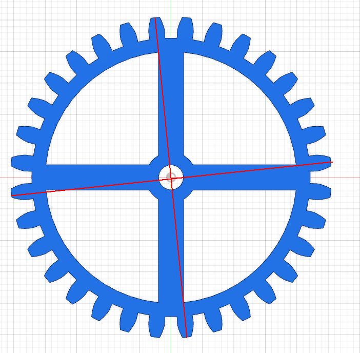
For illustration, here is the fit as seen in Fusion 360 between the seconds wheel and the escapement wheel:
One large square is 5mm. And here is the seconds wheel and the intermediate wheel:
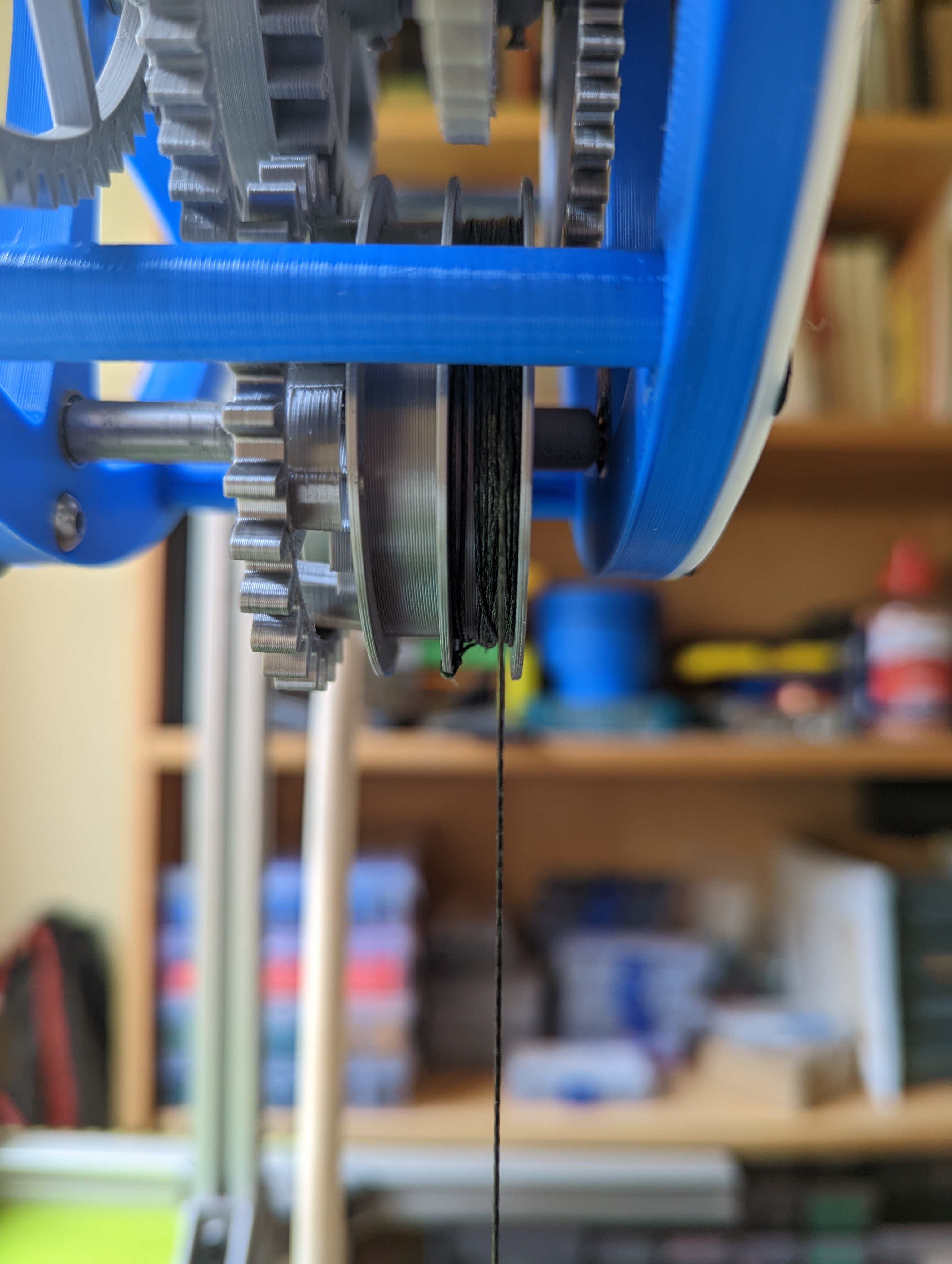
In prototype 4, I wanted to make more space for the weight drum without changing the overall dimensions of the clock. I worked out one way of doing this was to flip the direction of what I call G2, the gear immediately after the escape wheel, which drives the seconds hand. It changed from this (with the original, incorrect escape wheel):
to this:
By rotating it through 180 degrees and adjusting the vertical height of some of the other gears, it frees up lots of space on the main arbor. Now the weight drum has enough space for a counterweight, which can be used for winding, and there is also more clearance so that it doesn't rub against the hour wheel. Other rearrangements are possible, and I intend to look at these in a later version. The new weight drum, with sections for the weight cord and the counterweight cord can be seen here:
The counterweight cord had just come off in this picture. Apparently I am not very good at tying knots.
When I first put this together, it did not run well, and I could not get more than a few minutes from it. After a lot of experimentation, it looked like some of the gears didn't have enough clearance and were either seizing or adding friction. Notably, this occurred between the first itermediate gear (G3, between seconds pinion and minutes) and the second intermediate gear (G5, between minutes pinion and hour). I designed the gear without relaxing any tolerances other than allowing some backlash. I had some discussion with Steve Peterson about this and added gullet to G3 and truncated the teeth of the G4 pinion. Both helped a little but didn't fix the problem, and I was at the point of giving up on the design.
After a few days of mot thinking about clocks at all, I made up a depthing tool:
You can mount the gears on it and adjust their exact distance to see how it affects their running. I don't know that I can trust the exact distances I read from it, but I could see that in some cases, only a few tenths of a millimeter would change the gear pair from spinning loosely, to free but not as loose, to not being very free at all, based on an unscientific method of spinning them and seeing how long they took to stop.
This suggests that undersizing the gears might be a solution, and it also occurred to me to drill out the arbor holes slightly. After printing, I had drilled the holes in the frame out to 3.1mm diameter, and now I drilled them out to 3.2mm. More exactly, I used a 3.2mm drill. The holes might be a little larger as I drilled them by hand without being very precise about centering the drill. This seemed to make a huge difference, and I was able to get runs of 2 hours or more. I don't think that this makes the arbors run more smoothly in the holes in the frame. It's more likely that it is giving some wiggle room for the gears. There are still some issues, in particular I think G3 has some friction with the hub of G2. Here is a short video:
The face is loosely attached here. In the end it will have four fixings.
There are some things I still haven't done: the clutch for the minutes hand, and a smaller diameter weight drum. But after some frustration, I'm happy with this as prototype 4.
I've been round the following issue several times now, and so I thought I would document it, even if only for my own future reference. If you find that a Prusa MK3 is manifesting problems like:
- blobs (like little nodules) on the surface of prints; see the right hand example below.
- under extrusion and poor layer adhesion, especially when there is a lot of retraction
- slight extruder clicking
- in extreme cases, extruder motor overheating
then the problem may be that the axle for the extruder idler has slipped. This has happened to me several times now. Open up the extruder cover and see if it turns freely. If it feels graunchy, see if you can push the axle in slightly. The movement may then get smoother. If you push it too far, you won't be able to close the door over the idler and can pull it back a bit. This has fixed the problem for me now at least three times, including one case where the axle was slightly bent and needed to be replaced.
The latest prototype gets a bit closer to being a real clock. The frame is much more robust, and has a weight drum connected via a ratchet. Somehow I got a whole lot of things wrong in this version. It simply didn't run for more than a few seconds at first. The pendulum would swing for a short while and then stop. I spent a long time searching for sources of friction, and removing some parts of the mechanism such as the hour train and reprinting or drilling out others. This revealed a few things that could be improved. For example, the bearings for the fork arbor were very tightly fitted, and so unless they were exactly square, this put extra friction on the arbor. However, they real reason turned out to be that I had the fork inverted. The sketch I had constructed from it in Fusion 360 was for an escapement which turned the opposite way. In the earlier prototypes, I had remembered to invert the part but this time I didn't. As a consequence the pallets were oriented wrongly and didn't receive any push from the escape wheel teeth and the pendulum ran out of energy. A definite case of a short circuit between the ears. Once I had fixed this, things worked a lot better - still stalling sometimes, but I have had a test run of 4 hours with no problems.
Here's a video.
Now you might think this is recorded at half speed, but it isn't! It seems that I got the gear ratio between the escape wheel and the second wheel wrong. The pendulum is going at the right rate, but everything after that is wrong. The brain really wasn't working well the last few days.
A couple more pictures:
There are still plenty of things to fix or add:
the weight drum sometimes slips forward and rubs against the hour wheel. This maybe the cause of the stalling.
although there is a ratchet on the weight drum, I didn't arrange a mechanism for rewinding the clock, and some changes to the frame would be needed for it.
I included a clutch on the minute arbor, but didn't get it right. The clutch should allow you to turn the minute hand and have it also turn the hour train. This entails having the minute pinion securely fixed to the arbor and the main minute wheel able to slip. In yet another moment of vagueness, I got this the wrong way round.
I think a lot of this can be fixed using the same frame (or something very similar), by rearranging the position and orientation of some of the gears. The decision to arrange that all the gears have the same distance between their centers helps here.
For the next round of work on the new clock, I changed the configuration to have a frame which is shorter overall, and with the escapement set off to one side.
There is nothing holding the end of the side piece in place so it tends to splay out a little, but will do for this phase. (The illustration shows one version of the design. I used different minute wheels and weight drums in the experiments.)
For the first test, I made a minute wheel with a winding drum built into it, and set the clock going. With a weight of 560g, it ran for a few minutes and then stalled. Raising the weight to 680g, it ran until the weight hit the floor. The weights were not chosen with any care: I use a water bottle, and it's just a result of how much water I put in it.
Theory says that for a 50mm drum, you should unwind the string at 15.7 cm per hour if the motion is continuous. This means that for a typical 1.5 m drop, you would get a run time of around 9.6 hours. It's not enough for a practical clock, but will do while I am experimenting. I also added a weight drum on a separate arbor with 3:1 gearing.
(Yes, I know the string is tangled round the gear. It's the only video I took before disassembling it and I noticed it too late. It wasn't tangled when I did the tests.)
The 3:1 gearing triple the run time to 28.7 hours. However, I didn't get this arrangement to run reliably. It would usually stall after 10-15 minutes, though I did have one run lasting an hour. The weight I was using was 1340g (the heaviest I could get with a water bottle), and this probably explains it. You would expect something more like three times 680g, that is about 2kg, would be needed. I think the frame may also have been starting to distort slightly. Initially when I tried using the 3:1 gearing, I added a 20 tooth gear on the minute arbor, such that both it and the minute wheel were held onto the arbor with set screws. I could not get them to hold tightly enough and one or other would slip. In the end I glued the two gears together, and if I use this in future, I'll print them combined.
Finally, I put together a rough version a weight drum with a ratchet. I thought this would be straightforward, but ended up going through several variants. Looking at other clocks, I see three main styles:
the drum (which in all of these is within the diameter of the minute wheel) has a ratchet on on end, and there are pawls freely pivoted on the minute wheel. Gravity makes them drop into place. A lot of wooden clocks use this.
the drum has a ratchet on the end and there are sprung pawls attached rigidly to the minute wheel.
the ratchet is inside the wheel and the pawl are pushed outwards by spring. Used in Steve Peterson's SP5 (on a separate arbot).
The three styles are illustrated here:
(Credits: Jacque Favre Clock One, TheGoofy design on Thingiverse, Steve Peterson SP5).
I played around with the gravity approach for a bit, but found it hard to get the pawls to drop into place at the right time, and settled on using sprung pawls. They work at any position at any orientation and work well given that you can print thin springy plastic.
With a 50mm drum, I measured a weight drop of 8cm in 32 minutes, or about 15 cm/hour. There is something puzzling here as some other measurement showed quite different values. I also tried a drum 25mm in diameter. As expected, this halved the drop per hour. You would expect to have to increase the weight, but I got away with the same 680g, albeit with a rather weak tick. It would probably have stalled if I let it go on for longer.
I put the weight drum directly on the minute arbor for the tests I've just described. It is not a good way of doing things, as you really need the arbor with the weight to be supported at each end. That doesn't work well with some configurations of the hour train and works even less well if you are going to bring out a seconds arbor. As I mentioned before, a separate weight drum arbor with a 3:1 reduction didn't run without stalling, and so I decided to try 1:1 gearing. There should not be any problems with this, and indeed it worked fine. So this gives me the configuration I want to use for the next version, with the option that the 1:1 gearing could be changed.
Incidentally for some of these prints, I used a 0.6mm nozzle with an Arachne-based slicer (PrusaSlicer 2.5.0 alpha). Allegedly this gives as good precision as a 0.4mm nozzle. See Thomas Sanladerer's video for details. It seems to work well, though I still have a little bit of tuning to reduce stringing and blobbing, and it is more prone to producing elephant's foot. For now, it's good for faster prototyping, and I'll stick with 0.4mm when I want better accuracy.
It's about a year since I started making 3D printed clocks, with Steve Peterson's SP5 clock, and I decided it was time to try designing a clock of my own. I have modified some of the clocks I've made in small ways (adjusting fit) and in larger ones (replacing the motion work in the Swingtime clock). The only complete design I have done was the William Strutt epicyclic design, and even then much of it came from a published diagram. Now it's time to do something from the ground up. I don't know if I will carry this all the way through to a reliable design; it may turn out I don't have the skills or the patience to do so.
The starting point is a basic Graham escapement design with a rather conventional wheel train and motion train. I have a few ideas for ways I would like to refine it over time. The gear tooth counts are taken from this design on Thingiverse, itself remixed from a design by Thingiverse user TheGoofy. Having said that I wanted to design the clock myself, it might seem inconsistent to take the gearing from an existing design, but there are only so many possibilities which give you the right ratios and a number of teeth that you can manufacture. I like this wheel train as it allows you to add a seconds hand easily. Assuming a pendulum with a 2 second period (so about 1 metre long), you get this:
Escape wheel: 30 teeth, pinion 30 teeth.
Seconds wheel: 60 teeth, pinion 9 teeth.
Intermediate wheel: 72 teeth, pinion 10 teeth.
Minute wheel: 75 teeth, 16 teeth.
Reduction wheel (minutes to hours): 64 teeth, pinion 20 teeth.
Hour wheel: 60 teeth.
You have some choice about the gearing from the minute wheel to the weight drum. My initial design has an extra 20 tooth wheel on the minute arbor engaging with a 60 tooth wheel on the weight drum for a 3:1 reduction. If the weight drum has a diameter of 50mm, then it means that for each 3 hour rotation, the weight drops pi times 50mm, so that in 19 hours the weight drops by 1 metre. The pendulum length is something I will reconsider later.
I did the design in Fusion 360, using the standard add-in for generating the gears. The add-in only generates involute gears. I feel sure that I read something which said that cycloidal gears are better in the train from the weight to the escapement where each step increases speed and reduces torque, and involutes are better in the train from the minute wheel to the hour wheel, with the opposite characteristics. However, I could not find the reference again and there are many places which say to use involutes unless the teeth are so small they become fragile. This reference concisely summarizes the debate. If I wanted cycloidal gears there are tools like this one which output a DXF or SVG. I used a 14.5 degree pitch angle and a small amount of backlash to make the spacing between the teeth better. All of the pairs of gears are design to have their centers the same distance apart (60mm) so that I can stack several on the same arbor if I choose, leading to various different modules from 1.33 to 1.5. For the escape wheel and anchor, I used a parametric design a created a few months ago in Fusion 360, based on Jacque Favre's tutorial.
(Side note: what I actually did for the gear was use the add-in, and then project the profile into a new sketch. I could then project the pinion profile into a new sketch. This makes combining them a little easier.)
Here is a picture of a prototype, with a couple of minor parts missing:
The purpose of the prototype is to check everything seems to fit together. The weight arrangement is unfinished. It has no ratchet to allow for rewinding. The frame is very flimsy as I designed to print quickly. There are no bearings or attempt to reduce friction in this version, and the anchor is designed so I can experiment with different positions for the pendulum.
I printed part of this: the frame and the wheel train from the escapement through to the minute wheel, modified to include a weight drum. Originally I wanted to try this with various weights to get an idea of what weight I might need in the final version, but I had cut corners in the frame. So in the end it only ran for a few seconds with a weight hooked up. However, by applying force to the minute wheel by hand I was able to see it roughly working:
The beat isn't right and it takes quite a lot of force to make it run, but it gives an idea that things are generally correct.
In an earlier post, I wrote about splitting large gears into parts to print them on a Prusa MK3S. My current project includes a gear which is strictly larger than the official size of the print bed, but by using a trick you can still make it work.
The gear is 281.33mm in the Y direction from tooth tip to tooth tip. The Prusa MK3S print bed is 250x210mm. However, you can go beyond these limits. First, in the PrusaSlicer printer setting, change the bed size to 250x230mm with an origin offset of 10mm in Y, 10mm being half the difference 230 and 210. Now load the model, move it until it is within the printable area and slice it, with skirt turned off. If you just go ahead and print it, the printer may come up against its Y limits. Nothing terrible happens at this point. You can hear a slight "clunk" as it reaches the limit, and the print it truncated, like this:
The trick is now to adjust the Y position of the model so that we minimize the truncation at both top and bottom. I found that for this model, 103.5mm was the best compromise, leading to a very small amount of truncation:
This is probably OK as the very tips of the gear teeth are not doing much.
Note that you have to peel off the pressure release strip as soon as it has printed, otherwise the print overlaps it.
This looks to be about the limit of what is achievable. With a slightly smaller model you could avoid any truncation at all while still exceeding the official limits. I guess 217mm would be OK.
In my previous post about the Swingtime clock, I noted that the remontoire occasionally goes mad. The motor keeps running until the motor arm collides with the third wheel, long after the tilt switch should have turned it off. I was using a miniature tilt switch of the sort that has two metal balls inside it (like this). I replaced the component I used at first with a second one and got the same result after a day or so of running the clock. The original design called for a mercury tilt switch (like this) and so I replaced it with this one from Amazon. It's a little big for the compartment in the motor arm, but I found that if you open up the plastic package, the actual switch is only about a third of the size. I mounted it and the capacitor on a small piece of veroboard:
(I know its hard to see. You get the idea and the scale.)
It's too early to say whether this works better. However, I've run it for more than a day with no signs of problems. With the original tilt switch, even before the overrun and crash into the third wheel, I would sometimes see it running for longer than expected, and I have not noticed that happening at all with the new switch.
One problem remains with the clock: it occasionally squeaks. It is always on certain teeth of the escapement, though it does not squeak every time. Some polishing or lubrication should help. To find when it is happening, I've been taking video at 1/8 speed. Here is an example:
Update: after further examination, I think there was more than one source of the squeaking. It got less when I polished the tips of the escapement, and then went away completely after I lubricated the escape wheel arbor. (For now, at least...)
The Swingtime clock is a design by Clayton Boyer. I previously made his Toucan clock. Like the Toucan, the Swingtime is designed to be made out of wood, and I adapted it for 3D printing. I highly recommend watching this video to see how it works.
It's a large clock and this posed some challenges. The main wheel is slightly too large to print on my Prusa MK3S, and so I split it into two pieces, using the technique I described in a previous post. The hourglass-shaped pendulum itself is about 60cm from one end to the other. For this, I printed the center and the two ends, and then joined them together with wooden dowels. One end was still too large to fit the print bed, and so I also split it into two pieces. Finally, the frame is again too large. I found that by reducing it to the minimum size needed, roughly the distance from the escape arbor to the main arbor plus a little extra, it will just about fit diagonally on the print bed. Very long straight objects with a low contact area are one of the hardest things to print without warping. I got lucky and there was only the tiniest lifting from the bed at one end. The whole thing is mounted on a stand of 2020 aluminium. I have lots of this lying around from previous printers, and while it's not as elegant as a wooden stand it does the job. One concern I have is that the very top of the frame is unsupported and the escape arbor sags slightly as a result. I think it's OK, but it will need to be watched over time. I don't recall the amount of weight in pendulum bob, except that it was a lot less than the 140g suggested in the original design. I used some BBs, glued into the bob with wood glue so that they don't shift as the pendulum swings; it doesn't the operation if they do, just makes a slight noise.
Here's a few pictures and some video.
The original design uses a daisy wheel for dividing the minute rotation to the hour rotation. I used this in a previous clock, and I don't much like the motion it gives. As I noted in the previous post, there are two variants of the daisy wheel design. Clayton Boyer's design uses what I think is the less good one, as it causes the hour hand to move eccentrically. You can see the tip getting closer and further away from the clock face as it rotates. You can see this in another build of the clock, around the 2:50 mark. The daisy mechanism can also give a non-uniform movement in the sense that its angular speed changes as the minute hand advances. One alternative I considered was to use Ferguson's mechanical paradox, as in the William Strutt epicyclic clock. However, after trying several prototypes, I was still unsatisfied with the smoothness of the motion from it. In the end, I used a very conventional 3:1 and 4:1 gear train between the minutes and the hours. It floats freely on the back of the clock face.
The arbors are 5mm brass, with a 6mm brass tube for mounting the assembly containing the clock face, hands and minute/hour reduction. Each arbor has a small cap. As well as improving the appearance, it stops the gears from gradually sliding forward on the arbors. This was definitely necessary for the third wheel. The pallet rests on has two MR105, chosen because I had some in my parts stores from a previous project.
The clock is driven by a weight attached to an arm behind the minute gear. The arm contains a motor and a tilt switch. When it drops below a certain angle the motor engages and move the arm up a little. I didn't quite believe that this would work until I saw it happen: why doesn't the force of the motor just drive the minute wheel round rather than raising the motor arm? I think it's that there is enough resistance from the rest of the mechanism, or maybe the escapement is locking everything in place for the short time the motor runs. Or maybe I just don't understand physics. I found that the motor sometimes moved itself up then dropped back down again, similar to what you can see in the first few seconds here (same video as before). The comments thread for that video mentions that Clayton has a modification using a detent to stop this. I had considered something similar. An alternative is to add a capacitor to the motor. This charges up while the tilt switch is engaged and then keeps running the motor after the tilt switch turns off. The motor arm then lifts up a bit further until the capacitor has discharged. It has two beneficial effects: the motor arm raises further so it is longer before the motor has to run again; and as the charge on the capacitor decreases, the motor comes gradually to a halt, which seems to make it hold better. I used 4700uF. The tilt switch is a miniature kind, from here, and the motor is this one. The distance the motor travels on activation is very variable, anything from moving the motor arm through about 10 degrees to as much as 45 degrees.
If you look at the end of the video, you can see the remontoire going mad, and driving the motor arm until it collides with the third wheel. At first I though this was because the capacitor was too large, but I now think it was due to the tilt switch getting stuck. The switch contains a small metal ball which joins the contacts, and it's possible that I slightly squished the casing causing the ball to get stuck. It doesn't do this every time, for example the first time I saw it was after a couple of hours, and it clears after a short time. I'm currently trying a replacement tilt switch to see if it helps.
I like this clock a lot. Clayton's designs are elegant and work well. It looks wonderful and the broad slow swing of the pendulum is lovely to watch and listen to. I'm also emboldened to try some large designs that I would previously have rejected.
Sometimes I need to print objects which are too large to fit on the print bed by splitting them into parts. I've used this in particular for the frame of some clocks such as the Thriecan. I have been reluctant to use this for parts such as gears where the dimensions need to be precise. A project that I am working on calls for a gear too large for me to print, and so I decided to conduct an experiment to see if I can split it and still get a working gear. As with other split parts, I make some 1mm holes in the part and then use metal pins to get the parts into alignment, and glue them with a gel cyanoacrylate. I have been using Loctite UltraGel.
I made a test piece consisting of a gear about 50mm in diameter, with the split in the gap between teeth. This is the least critical place for functioning of the gear as it never comes into contact with any other gear. I did two versions of the split gear, for reasons which are explained in the "aesthetics" section.
The results look like this, with the unsplit gear at the top. First, the right way up, and the upside down, with the the side that was in contact with the print bed facing up. I did no finishing on the gears, as you can see from the stringiness. If you enlarge the pictures, the pins are visible. Normally I would trim them to size so that they are hidden.
Dimensional considerations
The most important factor is whether the size of the gear is correct, defined as similar for the split and unsplit versions. I measured the distance from the end of a tooth to the one diametrical opposite, across two axes at right angles. I chose the axes like this
so as to emphasize any effects from the split. For the unsplit gear, the axes measured 50.75 and 50.82mm; for the first split gear, 50.71 and 50.83mm; and for the second split gear, 50.58 and 50.89mm. The differences are negligible at this size of gear. They are likely to stay constant in the size of the gear, so by the time we get to something where the gear needs to be split to fit on the print bed (roughly 4 times the size here), they will be even less significant.
Mechanical considerations
A second consideration is whether the split will cause weakness in the gear that could affect its operation, either by causing it to deform during use or even to split apart altogether. I don't have any good way of evaluating this. For building clocks, it probably does not matter, as there is not usually a lot of mechanical stress extending across the halves of the gear except near the power source (drive weight, spring, etc.). Even so, the bond is strong. I was not able to pull apart the two halves of the gear except in one spot where I had not applied very much glue.
Aesthetic considerations
The split can look a bit ugly, or at least noticeable. You can see this quite clearly on the middle gear in the second picture. The third gear shows a possible solution to this, but adding a notch to both the spoke with the split and the other spokes, so they all look similar.
I think this post is mostly directed at my future self, as a reminder of what I did. Here goes anyway.
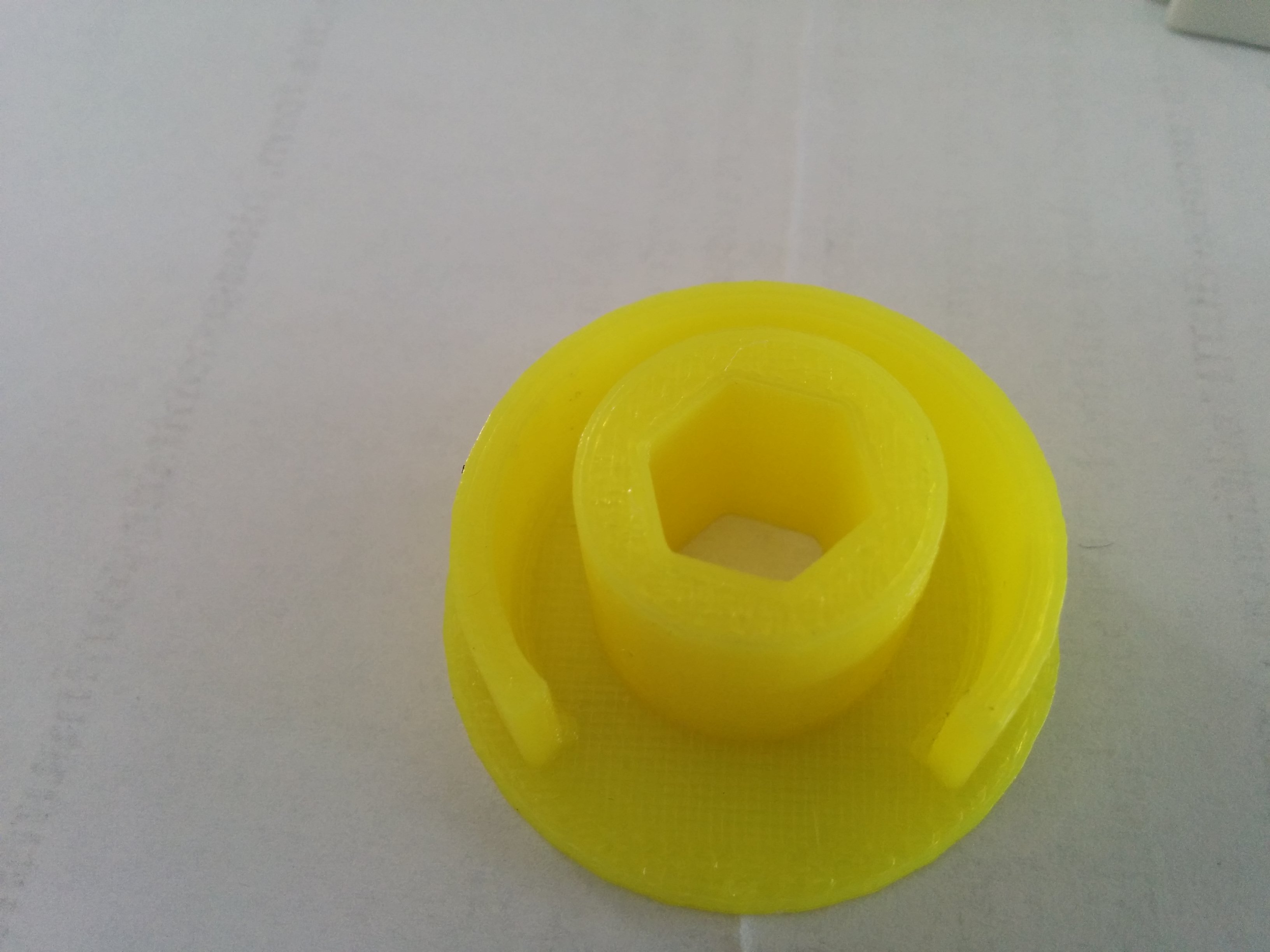
I have roller blinds in my house made by Mechoshade. They are the sort where you use a metal beaded cord to raise and lower it. Inside the mechanism there is a clutch, between the indented wheel which the cord engages with, and the hex-shaped shaft of the blind itself. The clutch for one of the blinds has failed multiple times. After the original failure, I printed a replacement in PLA:
This was in October 2015. I have not tracked how often it has failed since. It's probably two or three times. Usually I print the replacements at 0.2mm layers, 100% infill (if I remember), using PLA. I have tried PETG, which failed immediately. The most recent replacement was a few days ago, and I hope it will hold for a year or two. However, this got me thinking about other materials. Ideally you want something which is strong but not brittle. Strong, because the blind is heavy and I am not always gentle with the cord. Brittle materials tend to fail suddenly after multiple stress cycles, which seems likely to be the case here. PLA has the strength, but is also brittle. PETG didn't work because it is not very strong. A chart on Taulman's web pages gives a good guide to the material characteristics. I decided to look at nylon and two related filaments.
For Nylon itself, I bought a 200g roll from Gizmodorks. I didn't note the exact print settings I used. The results were not great. A first attempt had a poor finish with blobs all over the surface. I think this was at 250. A second attempt with a lower temperature had a better finish but the print delaminated. It is possible that the filament had not been kept well. Nylon is hygroscopic and some sites say that even a few hours exposure to the air will make it damp enough to cause problems. The print surface was blue tape with glue stick. Blue tape on its own was not enough, and when using an unknown filament I prefer not to use PEI sheets so as not to risk damaging them.
Next, I tried Taulman PCTPE. As I understand it, this is a mixture of nylon and a flexible filament similar to TPU. I used it once before, a long time ago, to make a headphone holder and found it to be very strong. For the print settings, I started with one of the flexible filament profiles in PrusaSlicer, and increased the volumetric flow rate to 5mm^3/s. Initial attempts on blue tape warped. Blue tape with glue stick worked. I also started with 240/50 and then reduced it to 220/50 for the successful print. You can hear bubbles popping a higher temperature and see water vapor coming off it. The result is quite flexible, possibly too much for the clutch.
Finally, I tried Taulman 910. This is supposed to be very strong under tension, while still having some flexibility. Some people say it is hard to print with and needs a high temperature and an enclosure. For met it worked fine at 240/50 on blue tape with no need for glue stick. The result is a little more flexible than I expected. It definitely feels strong; I have no way of evaluating this more precisely.
Warped PCTPE:
PCTPE and 910:
(Sorry for the poor pics. My camera was having difficulty focussing.)
I have not fitted the new clutches yet. It's a nuisance to take the blind apart so I'll wait until it fails again. This might not be for a year or two.
Jacques Favre has designed several interesting clocks, the designs for which are available on myminifactory. I built his Clock 24 design. It is weight driven, and uses a Graham escapement. The run time when it is mounted at a reasonable height (5 feet or so) is about 24 hours. This could be increased by using doubling the weight cord through a pulley.
One striking thing about Clock 24 compared to all of the others that I've made is that it is huge. The scape wheel and largest gears are almost twice the diameter of the ones in the first Peterson clock and the frame is corresponding larger. It uses arbors of 5mm and 2mm diameter, compared to 3mm and 1.5mm in the Peterson clock. I'm not sure of the consequences of this for ease of getting it going. I think it probably makes it a little less sensitive to printing tolerances. Does it make it more or less sensitive to friction? The contact area with the arbors is larger (more friction) but bears less force per unit area (less friction). I just don't know. As with previous clocks, I used brass rods for the arbors as it's easy to cut them without power tools.
I found it quite easy to get going after a made a few small adjustments; mostly adding some extra washers to keep some of the gears clear of each other. There are a few variants for the design, the most interesting being in the mechanism which goes between then main gear train (known as the going train) and the winding gear (which carries the weight). This can either be two gears with a simple ratchet, or a more complex design with a spring to act as a power reserve for the going train during winding. I elected to go with the simpler option. The escape wheel also has two variants, one with full depth teeth and one with tapered teeth which may have lower friction. I started with the tapered version, but found that the anchor tended to wobble as it only has a small area of contact with the escape wheel teeth. The non-tapered version worked better.
One interesting design choice is the clutch. In the Peterson clock, this is done by a spring which holds a gear and a spacer in contact. The Clayton Boyer design that I built uses a small pad of leather held against the arbor with set screw. Favre's clutch sandwiches the arbor between two metal rods with screws to adjust how tightly it is held. I didn't take a picture before assembling the clock but perhaps you can see it here:
Or perhaps not.
I am still testing the clock. I have the timing quite well tuned now. The weight is about 1.3kg; less might work. As I write this, it has been running for a bit over 12 hours continuously. A couple of previous runs stopped after 1-2 hours and it seems that something was binding. Some of the previous clocks have stopped when friction has consumed too much of the power of the clock. You see the pendulum losing more and more of it swing and finally dropping below the amount needed to engage with the escape wheel. When Clock 24 stopped, it seemed more like something in the gear train had locked up, and it took a nudge to free it and get things going. It may be that the gear can't move freely enough on the arbors (not enough endshake maybe). If it binds again, I'll see if I can get a better idea of what is going on.
I recently completed a couple of new clocks, both brief experiments.
Neopixel clock
The first uses a circular array of WS2812 LEDs, sometimes known as neopixels. It's hard to take good pictures of it, as the brightness of the LEDs overwhelms the camera on my phone. This will give a general idea:
The LEDs are this product. It consists of several concentric rings which different numbers of pixels. It's a nice, cheap product and comes with connectors so that you can use just some of the rings and address them in any order. The only alternative I found was an overpriced product from Adafuit.
The outermost ring has 60, making it suitable for minutes and seconds, and the next has 48, meaning you can displays hours down to quarter-hour resolution. I use the next ring, with 40 pixels for a temperature display, although that part of the software is not complete. The controller is a M5StickC Plus. Strictly speaking a level shifter should be used between the 3.3V output of the ESP32 in the M5, and the 5V needed for the control pin of the pixels, but it seemed to work OK without one. The only problem I had was during prototyping when I had it connected up through leads with alligator clips. For some reason, the signals got corrupted in this case. Using a breadboard or soldered connections works fine. The hours and minutes are displayed as a sort of swoosh with several LEDs at different brightnesses. The case is 3D printed in clear PLA. This does make the pixels a bit fuzzy, though most of the fuzziness in the video is from the camera.
The neopixel clock is not very practical. It's surprisingly hard to read the time without hands to direct your eye. I hoped the swooshes would help, but they really don't: every time I look at it, it takes a few seconds to read off the time, when it ought to be near-instantaneous.
Favre's Full Clock
The second recent build is Jacques Favre's "full clock". It's a straightforward clock mechanism driven by a small stepper motor, the widely used 28BYJ48. I used the ULN8003 driver board that came with the one I bought instead of the L293D preferred by Favre. The clock needs two 608 bearings, and there are printable versions. I had several 608s in stock, so used them instead.
The clock runs silently and smoothly. I like this design better than Steve Peterson's stepper clock (see this post), which is not quite as quiet and slightly jouncy in its movement. One concern is whether the 28BYJ48 will stand up to continuous running as they aren't really designed for it.
I am thinking of making some of Favre's other clocks, and this short project was meant as a way of learning more about his design style. Almost all of the parts worked fine. The only modifications I made were to shrink two parts with an inner thread by 95% for a better fit, and to make the hands a bit less boxy. There are some shafts glued together from two halves and I made 1mm diameter holes in them so I could use a pin or piece of wire to keep them aligned while the glue set.
Peterson 10 day clock update
Steve Peterson's 10 day clock was the first one I made. One problem I have had with it is that after a few weeks of running, the pendulum amplitude gets less and less until it stalls. Reading the comments thread on his myminifactory page, this is a problem which several people have had. The proposed solution is always to find ways of reducing friction, and I have been through several cycles of doing so: re-cleaning the bearings, polishing the arbors, reprinting the gears in regular PLA instead of silk PLA, lubricating with white lithium grease. I also tried adding more weight. The pattern has been the same every time: it seems good at first, but after 4-6 weeks of use, the problem recurs. I'm now trying ceramic bearings to again try to bring down the friction. We'll see what happens.