In prototype 4, I wanted to make more space for the weight drum without changing the overall dimensions of the clock. I worked out one way of doing this was to flip the direction of what I call G2, the gear immediately after the escape wheel, which drives the seconds hand. It changed from this (with the original, incorrect escape wheel):

to this:

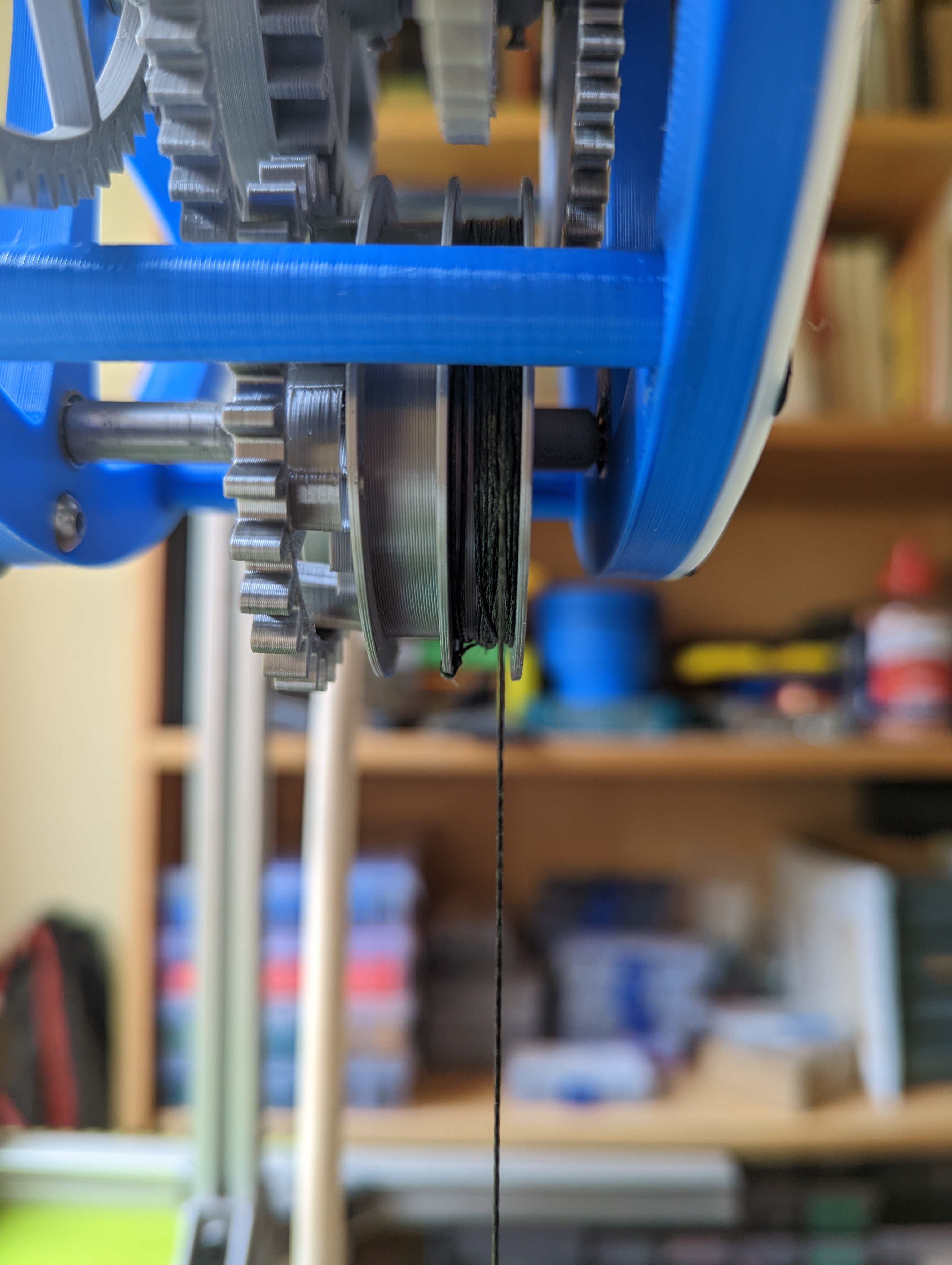
By rotating it through 180 degrees and adjusting the vertical height of some of the other gears, it frees up lots of space on the main arbor. Now the weight drum has enough space for a counterweight, which can be used for winding, and there is also more clearance so that it doesn't rub against the hour wheel. Other rearrangements are possible, and I intend to look at these in a later version. The new weight drum, with sections for the weight cord and the counterweight cord can be seen here:
The counterweight cord had just come off in this picture. Apparently I am not very good at tying knots.
When I first put this together, it did not run well, and I could not get more than a few minutes from it. After a lot of experimentation, it looked like some of the gears didn't have enough clearance and were either seizing or adding friction. Notably, this occurred between the first itermediate gear (G3, between seconds pinion and minutes) and the second intermediate gear (G5, between minutes pinion and hour). I designed the gear without relaxing any tolerances other than allowing some backlash. I had some discussion with Steve Peterson about this and added gullet to G3 and truncated the teeth of the G4 pinion. Both helped a little but didn't fix the problem, and I was at the point of giving up on the design.
After a few days of mot thinking about clocks at all, I made up a depthing tool:

You can mount the gears on it and adjust their exact distance to see how it affects their running. I don't know that I can trust the exact distances I read from it, but I could see that in some cases, only a few tenths of a millimeter would change the gear pair from spinning loosely, to free but not as loose, to not being very free at all, based on an unscientific method of spinning them and seeing how long they took to stop.
This suggests that undersizing the gears might be a solution, and it also occurred to me to drill out the arbor holes slightly. After printing, I had drilled the holes in the frame out to 3.1mm diameter, and now I drilled them out to 3.2mm. More exactly, I used a 3.2mm drill. The holes might be a little larger as I drilled them by hand without being very precise about centering the drill. This seemed to make a huge difference, and I was able to get runs of 2 hours or more. I don't think that this makes the arbors run more smoothly in the holes in the frame. It's more likely that it is giving some wiggle room for the gears. There are still some issues, in particular I think G3 has some friction with the hub of G2. Here is a short video:
The face is loosely attached here. In the end it will have four fixings.
There are some things I still haven't done: the clutch for the minutes hand, and a smaller diameter weight drum. But after some frustration, I'm happy with this as prototype 4.
No comments:
Post a Comment