Thursday, August 25, 2022

Last experiments with prototype #4

For a last round of experiments on prototype 4, I looked at the effect of the weight and drum size. I had been fixing the seconds wheel to its arbor with a set screw. I think this still resulted in extra friction, either from constraining the meshing with the other gears, or (more likely) because of friction between the seconds arbor and the minute tube. For the next experiments, I removed the set screw. The second arbor (and hand) no longer turn, of course, but the friction is significantly less.

How does the weight affect the running of the clock? I tried different weights, and in each case measured the swing of the pendulum against a ruler. Some minor trigonometry turns this into the swing in degrees, each side of the center. Here's a graph of how things change, showing the angle against the weight in grammes. The values are approximate:


Two things are noticeable here. First, in this low friction configuration, you can reduce the weight to a really low value. It would still just about run with only 160g, though at this level any slight upset (such as a strong draft of air) could stop it. Second, it's really apparent that a small relative increase in the weight matters a lot more for small weights than for larger ones: the relationship is not linear.

I measured the the weight to drop at about 17.6 cm/hour. The drum is 50mm in diameter, so you expect this to be more like 15.7 cm/hour. I haven't adjust the pendulum length, and I estimate the clock is running about 10% fast, so from it's point of view, it is 17.6cm per 66 minutes, which is 16.0 cm/hr, closer to what it should be. At this rate, the clock would run for 10 hours on a 1.6m (5 foot) drop.

Next, I swapped out the weight drum for one with half the diameter. Now we would expect 7.85 cm/hr. The measured value was 9.4 cm/hr, or after correcting for the clock running fast 8.5 cm/hr. It's a bigger discrepancy than before; I'm not sure why. This would give a run time of a little under 19 hours. The minimum weight in this case was around 400g. Even with my larger 1100g weight, the running was a little flaky, and this proved to be that minute wheel was sliding backwards on it arbor and sometimes interfering with the escape wheel. As I've iterated on the design, I've been using slacker tolerances on the spacers, and I think I've taken it too far.

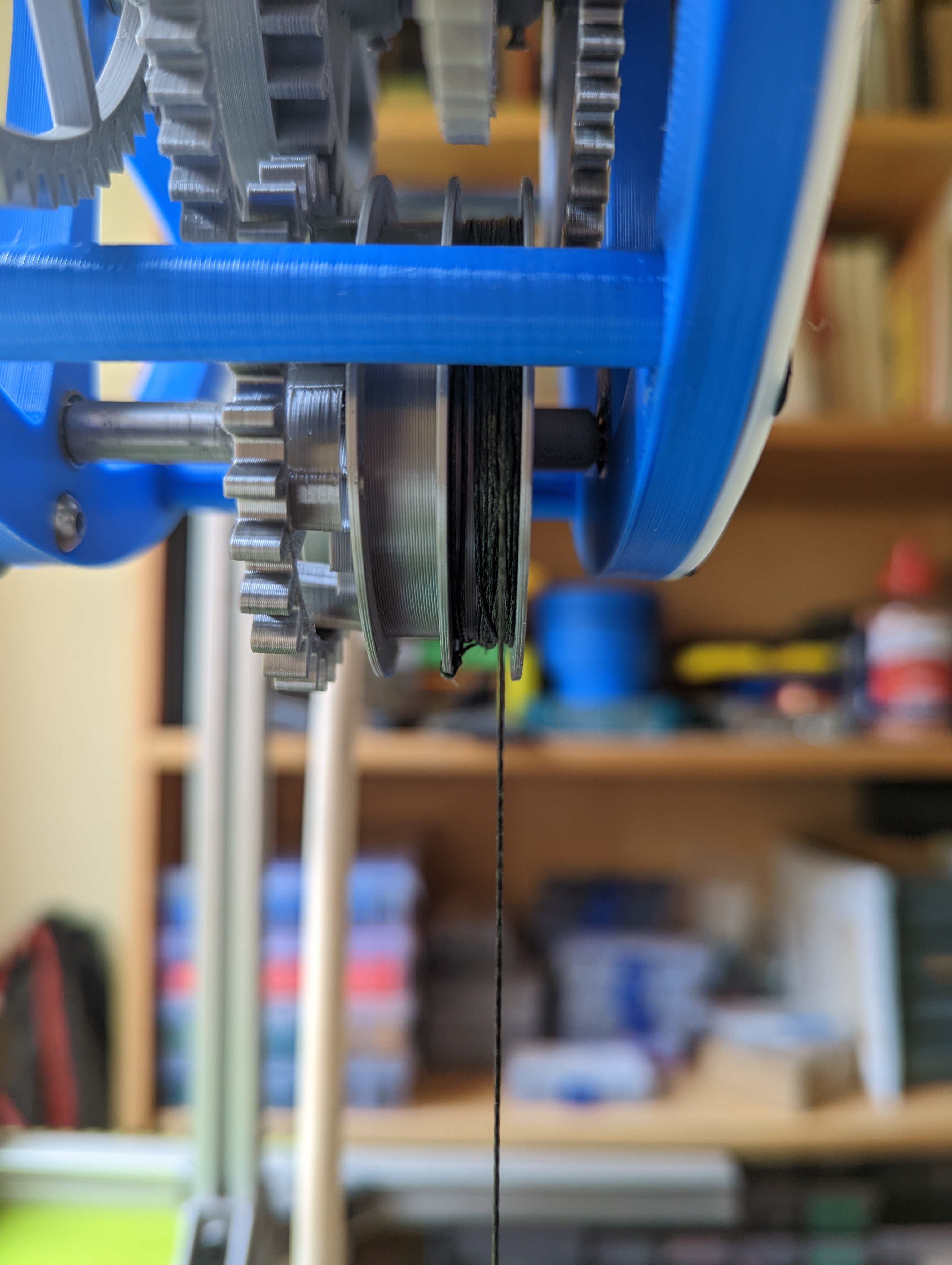
Finally I did a crude version of doubling by looping the weight cord through the top of the weight and clipping the end of it to the frame. It runs, though a little weakly at 1100g, giving 4.8 cm/hr. After the 10% correction, this would run for 37 hours on a 1.6m drop, which is starting to look good.

The smallest weight I tried was around 700g, and it ran better with this than I expected.

I wanted to try using a reduction gear from the weight to the minute wheel, but the frame design doesn't allow enough space for anything other than 1:1.

What next?

This is as far as I intend to take prototype 4. I have a number of ideas for the next version:

  1. Change to cycloidal gears. There is some argument that they have lower friction (ref 1, ref 2), though I think I have seen this disputed. In any case, redesign the gears so that there is more clearance.
  2. Change the geometry by flipping G1 to put the escape part at the front and the pinion (gear) at the back. Then G2 can be flipped as well. This may help reduce the change of G3 running into the G2 hub.
  3. Make a fixed position for the pendulum. It still needs to be movable, to set the beat, but the experiments I did on its horizontal position show that it doesn't matter.
  4. Stronger clicks in the ratchet. One broke off.
  5. Redesign the escape wheel teeth. This goes with the previous one. They need to be designed to that the slice better. Currently both of them have odd profiles due to the slicer switching the number of perimeters at the narrow points.
  6. Make the two intermediate wheels, G3 and G5, smaller, by changing the gear ratios around. The point of this is so that the pillars between the front and back of the clock can be moved to make more space for different ratios in the winding gear. Alternatively make pillars which are curved to allow extra space.
  7. Consider changing the period of the pendulum, and the number of teeth on the escapement gear and the seconds wheel so that they are not commensurate (i.e. don't have prime factors in common). This reduces the risk of a specific pair of gear teeth being a problem.
  8. Change the seconds, minutes and hours arrangement that end up at the hands. In prototype 4, the seconds arbor is a 3mm rod, the minutes uses a brass 4mm tube, and the hours uses a printed tube as part of the gear. I'm considering an arrangement where there is a 3mm arbor (or smaller) rigidly fixed into the frame, and each of the seconds, minutes and hours gears has a printed tube, nested on the arbor. It will take more space but might overcome the extra friction I think I saw when the seconds wheel was rigidly fixed to the arbor. Other options might work here.
  9. Make the spacers have stricter tolerances. You want some endshake on each gear, but they have become too slack as I've made the tolerances gradually looser.

Sunday, August 21, 2022

Clock prototype #4 again: a problem really solved

After my optimism about prototype #4, I reassembled it to make some minor tweaks, and found it was back to stalling. Something I noticed was that the tick got louder and quieter, and this was happening on a 60 second cycle. So that made it pretty clear that something was causing friction in one of the gears with this period, either the escapement wheel or the seconds wheel, or there was a problem in the interaction between them. The clock didn't always stall then the tick got weak, but eventually due to some random factor there would be too little energy to keep the pendulum going. To try to work out the cause, I marked a reference position on both gears, and then moved the position of one relative to the other. I could see that when the clock stalled, the second gear was always in the same position, but the position of the escape wheel didn't matter. The second gear is held on the seconds arbor with a set screw, and the position of this suggested that it displaced the second gear slightly towards the escape wheel, corresponding to the lowest energy, highest friction position. Some clock designs prefer to make the gear tight on the arbor. I don't do this, as it makes it hard to adjust the gear position, and over time it may start to slip. However, with the tolerance issues on the gears I mentioned in the previous post, it was enough to make the gears too tight. I proved this by removing the set screw and seeing that the clock ran well, though of course the seconds hand then didn't turn. A more durable solution was to slightly drill out the escapement arbor to 1.7mm, in the same way I drilled out the other arbors. After this, we were back to reliability. For now :-)

For illustration, here is the fit as seen in Fusion 360 between the seconds wheel and the escapement wheel:


One large square is 5mm. And here is the seconds wheel and the intermediate wheel:


The clearance is only about 0.3mm in each case.


Friday, August 19, 2022

Clock prototype #4, including a problem solved

In prototype 4, I wanted to make more space for the weight drum without changing the overall dimensions of the clock. I worked out one way of doing this was to flip the direction of what I call G2, the gear immediately after the escape wheel, which drives the seconds hand. It changed from this (with the original, incorrect escape wheel):

to this:


By rotating it through 180 degrees and adjusting the vertical height of some of the other gears, it frees up lots of space on the main arbor. Now the weight drum has enough space for a counterweight, which can be used for winding, and there is also more clearance so that it doesn't rub against the hour wheel. Other rearrangements are possible, and I intend to look at these in a later version. The new weight drum, with sections for the weight cord and the counterweight cord can be seen here:


The counterweight cord had just come off in this picture. Apparently I am not very good at tying knots.

When I first put this together, it did not run well, and I could not get more than a few minutes from it. After a lot of experimentation, it looked like some of the gears didn't have enough clearance and were either seizing or adding friction. Notably, this occurred between the first itermediate gear (G3, between seconds pinion and minutes) and the second intermediate gear (G5, between minutes pinion and hour). I designed the gear without relaxing any tolerances other than allowing some backlash. I had some discussion with Steve Peterson about this and added gullet to G3 and truncated the teeth of the G4 pinion. Both helped a little but didn't fix the problem, and I was at the point of giving up on the design.

After a few days of mot thinking about clocks at all, I made up a depthing tool:

You can mount the gears on it and adjust their exact distance to see how it affects their running. I don't know that I can trust the exact distances I read from it, but I could see that in some cases, only a few tenths of a millimeter would change the gear pair from spinning loosely, to free but not as loose, to not being very free at all, based on an unscientific method of spinning them and seeing how long they took to stop.

This suggests that undersizing the gears might be a solution, and it also occurred to me to drill out the arbor holes slightly. After printing, I had drilled the holes in the frame out to 3.1mm diameter, and now I drilled them out to 3.2mm. More exactly, I used a 3.2mm drill. The holes might be a little larger as I drilled them by hand without being very precise about centering the drill. This seemed to make a huge difference, and I was able to get runs of 2 hours or more. I don't think that this makes the arbors run more smoothly in the holes in the frame. It's more likely that it is giving some wiggle room for the gears. There are still some issues, in particular I think G3 has some friction with the hub of G2. Here is a short video:

The face is loosely attached here. In the end it will have four fixings.

There are some things I still haven't done: the clutch for the minutes hand, and a smaller diameter weight drum. But after some frustration, I'm happy with this as prototype 4.


Sunday, August 07, 2022

Prusa extruder axle problems

I've been round the following issue several times now, and so I thought I would document it, even if only for my own future reference. If you find that a Prusa MK3 is manifesting problems like:

- blobs (like little nodules) on the surface of prints; see the right hand example below.

- under extrusion and poor layer adhesion, especially when there is a lot of retraction

- slight extruder clicking

- in extreme cases, extruder motor overheating

then the problem may be that the axle for the extruder idler has slipped. This has happened to me several times now. Open up the extruder cover and see if it turns freely. If it feels graunchy, see if you can push the axle in slightly. The movement may then get smoother. If you push it too far, you won't be able to close the door over the idler and can pull it back a bit. This has fixed the problem for me now at least three times, including one case where the axle was slightly bent and needed to be replaced.


Friday, August 05, 2022

Clock prototype #3

The latest prototype gets a bit closer to being a real clock. The frame is much more robust, and has a weight drum connected via a ratchet. Somehow I got a whole lot of things wrong in this version. It simply didn't run for more than a few seconds at first. The pendulum would swing for a short while and then stop. I spent a long time searching for sources of friction, and removing some parts of the mechanism such as the hour train and reprinting or drilling out others. This revealed a few things that could be improved. For example, the bearings for the fork arbor were very tightly fitted, and so unless they were exactly square, this put extra friction on the arbor. However, they real reason turned out to be that I had the fork inverted. The sketch I had constructed from it in Fusion 360 was for an escapement which turned the opposite way. In the earlier prototypes, I had remembered to invert the part but this time I didn't. As a consequence the pallets were oriented wrongly and didn't receive any push from the escape wheel teeth and the pendulum ran out of energy.  A definite case of a short circuit between the ears. Once I had fixed this, things worked a lot better - still stalling sometimes, but I have had a test run of 4 hours with no problems.

Here's a video.

Now you might think this is recorded at half speed, but it isn't! It seems that I got the gear ratio between the escape wheel and the second wheel wrong. The pendulum is going at the right rate, but everything after that is wrong. The brain really wasn't working well the last few days.

A couple more pictures:


There are still plenty of things to fix or add:
  • the weight drum sometimes slips forward and rubs against the hour wheel. This maybe the cause of the stalling.
  • although there is a ratchet on the weight drum, I didn't arrange a mechanism for rewinding the clock, and some changes to the frame would be needed for it.
  • I included a clutch on the minute arbor, but didn't get it right. The clutch should allow you to turn the minute hand and have it also turn the hour train. This entails having the minute pinion securely fixed to the arbor and the main minute wheel able to slip. In yet another moment of vagueness, I got this the wrong way round.
I think a lot of this can be fixed using the same frame (or something very similar), by rearranging the position and orientation of some of the gears. The decision to arrange that all the gears have the same distance between their centers helps here.